Ethernet connectivity
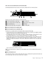
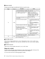
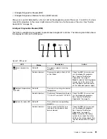
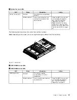
There are three RJ-45 Ethernet connectors on the rear panel with 10 megabits per second (Mbps), 100
Mbps, or 1000 Mbps network connectivity. The Ethernet connector 0 is for system management by default.
However, you also can set the Ethernet connector 1 or 2 for system management use in the Setup Utility
program. See “Setting the mode of the Ethernet connectors” on page 65.
For more information, see “Rear view of the server” on page 27.
Reliability, availability, and serviceability
Reliability, availability, and serviceability (hereinafter referred to as RAS) are three important server design
features. The RAS features help you to ensure the integrity of the data stored on the server, the availability of
the server when you need it, and the ease with which you can diagnose and correct problems.
Your server has the following RAS features:
•
Security features
– Administrator password and user password to help protect unauthorized access to the server (see
– ThinkServer Trusted Platform Module (TPM), which is a security chip, to help enhance server security
Note:
The TPM is only available in some models.
– Remote monitoring or control by an administrator to provide protection or help
– Hot-swap redundant power supplies to help avoid significant interruption to the operation of the
system when a power supply fails
– Six hot-swap system fans with redundancy, which means that five system fans can provide adequate
cooling while the extra one serves as a redundant system fan, to help you to avoid significant cooling
problems when a system fan fails
•
Basic system management features
– Ability to store the power-on self-test (POST) hardware test results
– BIOS Setup Utility program
The BIOS Setup Utility program helps you view the server information and configure the server in the
pre-operating system environment. See “Using the Setup Utility program” on page 59.
– TMM (also known as BMC) and Intelligent Platform Management Interface (IPMI) 2.0
The system board platform management subsystem is based on the integrated TMM features. The
TMM is a management chip that is integrated on the system board of your server. With the TMM, no
matter what condition the server operating system is in and no matter if the server is on or off, as long
as the server is connected to network and an ac power source, the interaction with the TMM-controlled
servers can be achieved through system network. The user can obtain the server hardware health
information and system event log (SEL), and is able to conduct the operations including turning on or
off the server, restarting the server, and so on. This part of server management is independent of the
operating system and is called out-of-band management.
The system board platform management subsystem consists of the integrated TMM, communication
buses, sensors, the BIOS, and server management firmware. It is responsible for error reporting,
system power control, thermal monitoring, system fan control, and other management features. The
TMM provides system management and monitoring features based on the IPMI 2.0 specification. IPMI
helps lower the overall costs of server management. You can find more information about IPMI 2.0
from the Web site of Intel. The TMM also supports some non-IPMI features, such as the Dynamic Host
Configuration Protocol (DHCP) and the Platform Environment Control Interface (PECI), to provide
more system management functions.
10
ThinkServer RD640 User Guide and Hardware Maintenance Manual
Summary of Contents for ThinkServer RD640
Page 14: ...xii ThinkServer RD640 User Guide and Hardware Maintenance Manual ...
Page 18: ...4 ThinkServer RD640 User Guide and Hardware Maintenance Manual ...
Page 20: ...6 ThinkServer RD640 User Guide and Hardware Maintenance Manual ...
Page 70: ...56 ThinkServer RD640 User Guide and Hardware Maintenance Manual ...
Page 202: ...188 ThinkServer RD640 User Guide and Hardware Maintenance Manual ...
Page 212: ...198 ThinkServer RD640 User Guide and Hardware Maintenance Manual ...
Page 228: ...214 ThinkServer RD640 User Guide and Hardware Maintenance Manual ...
Page 229: ......
Page 230: ......

