background image

ThinkServer RS110 Types 6435, 6436, 6437 and 6438

Hardware Maintenance Manual

Summary of Contents for ThinkServer RS110

Page 1: ...ThinkServer RS110 Types 6435 6436 6437 and 6438 Hardware Maintenance Manual ...

Page 2: ......

Page 3: ...ThinkServer RS110 Types 6435 6436 6437 and 6438 Hardware Maintenance Manual ...

Page 4: ...on 2007 2008 LENOVO products data computer software and services have been developed exclusively at private expense and are sold to governmental entities as commercial items as defined by 48 C F R 2 101 with limited and restricted rights to use reproduction and disclosure LIMITED AND RESTRICTED RIGHTS NOTICE If products data computer software or services are delivered pursuant a General Services A...

Page 5: ...ram 17 Using the WebBIOS Configuration Utility 24 Using the LSI Logic Configuration Utility program 24 Configuring the Gigabit Ethernet controllers 25 Updating the DMI SMBIOS data 25 Chapter 3 Parts listing RS110 Types 6435 6436 6437 and 6438 server 27 Types 6435 28 Types 6436 32 Types 6437 37 Types 6438 42 Power cords 47 Chapter 4 Removing and replacing server components 57 Installation guideline...

Page 6: ...es 94 Installing the SAS backplane 2 5 inch drives 94 Removing the SAS SATA controller hot swap models 95 Installing the SAS SATA controller hot swap models 96 Removing a drive cage 97 Installing a drive cage 97 Removing and replacing FRUs 98 Microprocessor 98 Removing the system board 104 Installing the system board 105 Chapter 5 Diagnostics 107 Diagnostic tools 107 POST 107 POST beep codes 108 E...

Page 7: ...vices 219 Lenovo Taiwan product service 219 Appendix B Notices 221 Trademarks 222 Important notes 222 Waste electrical and electronic equipment WEEE notices 223 Battery return program 224 Electronic emissions notices 225 Federal Communications Commission FCC statement 225 Industry Canada Class A emission compliance statement 226 Avis de conformité à la réglementation d Industrie Canada 226 Austral...

Page 8: ...vi ThinkServer RS110 Types 6435 6436 6437 and 6438 Hardware Maintenance Manual ...

Page 9: ...en lue turvaohjeet kohdasta Safety Information Avant d installer ce produit lisez les consignes de sécurité Vor der Installation dieses Produkts die Sicherheitshinweise lesen Prima di installare questo prodotto leggere le Informazioni sulla Sicurezza Les sikkerhetsinformasjonen Safety Information før du installerer dette produktet Antes de instalar este produto leia as Informações sobre Segurança ...

Page 10: ...that the exterior cover is not damaged loose or broken and observe any sharp edges 3 Check the power cord v Make sure that the third wire ground connector is in good condition Use a meter to measure third wire ground continuity for 0 1 ohm or less between the external ground pin and the frame ground v Make sure that the power cord is the correct type as specified in Power cords on page 47 v Make s...

Page 11: ... the off position v Never assume that power has been disconnected from a circuit Check it to make sure that it has been disconnected v If you have to work on equipment that has exposed electrical circuits observe the following precautions Make sure that another person who is familiar with the power off controls is near you and is available to turn off the power if necessary When you are working wi...

Page 12: ...nformation document For example if a caution statement is labeled Statement 1 translations for that caution statement are in the Safety Information document under Statement 1 Be sure to read all caution and danger statements in this document before you perform the procedures Read any additional safety information that comes with the server or optional device before you install the device x ThinkSe...

Page 13: ...equipment when there is evidence of fire water or structural damage v Disconnect the attached power cords telecommunications systems networks and modems before you open the device covers unless instructed otherwise in the installation and configuration procedures v Connect and disconnect cables as described in the following table when installing moving or opening covers on this product or attached...

Page 14: ...y with the same module type made by the same manufacturer The battery contains lithium and can explode if not properly used handled or disposed of Do not v Throw or immerse into water v Heat to more than 100 C 212 F v Repair or disassemble Dispose of the battery as required by local ordinances or regulations xii ThinkServer RS110 Types 6435 6436 6437 and 6438 Hardware Maintenance Manual ...

Page 15: ...he device v Use of controls or adjustments or performance of procedures other than those specified herein might result in hazardous radiation exposure DANGER Some laser products contain an embedded Class 3A or Class 3B laser diode Note the following Laser radiation when open Do not stare into the beam do not view directly with optical instruments and avoid direct exposure to the beam Class 1 Laser...

Page 16: ... and the power switch on the power supply do not turn off the electrical current supplied to the device The device also might have more than one power cord To remove all electrical current from the device ensure that all power cords are disconnected from the power source 1 2 xiv ThinkServer RS110 Types 6435 6436 6437 and 6438 Hardware Maintenance Manual ...

Page 17: ...has this label attached There are no serviceable parts inside these components If you suspect a problem with one of these parts contact a service technician Statement 26 CAUTION Do not place any object on top of rack mounted devices This server is suitable for use on an IT power distribution system whose maximum phase to phase voltage is 240 V under any distribution fault condition Safety xv ...

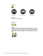
Page 18: ...xvi ThinkServer RS110 Types 6435 6436 6437 and 6438 Hardware Maintenance Manual ...

Page 19: ...n the Lenovo ThinkServer Documentation DVD It contains instructions for setting up the server and basic instructions for installing some optional devices v User Guide This document is in Portable Document Format PDF on the ThinkServer Documentation DVD It provides general information about the server including information about features and how to configure the server It also contains detailed ins...

Page 20: ...are also in the multilingual Safety Information document which is on the ThinkServer Documentation DVD Each statement is numbered for reference to the corresponding statement in the Safety Information document The following notices and statements are used in this document v Note These notices provide important tips guidance or advice v Important These notices provide information or advice that mig...

Page 21: ...ations of the server Depending on the server model some features might not be available or some specifications might not apply Racks are marked in vertical increments of 4 45 cm 1 75 inches Each increment is referred to as a unit or U A 1 U high device is 1 75 inches tall Chapter 1 Introduction 3 ...

Page 22: ...ter II SlimLine is installed Hard disk controllers v Serial ATA SATA controller simple swap SATA models v Serial attached SCSI SAS controller with integrated RAID hot swap SAS SATA models that supports RAID levels 0 1 1E Environment v Air temperature Server on 10 to 35 C 50 0 to 95 0 F altitude 0 to 914 4 m 3000 ft Server on 10 to 32 C 50 0 to 89 6 F altitude 914 4 m 3000 ft to 2133 6 m 7000 ft Se...

Page 23: ... the server The LED might be burned out To remove all electrical power from the server you must disconnect the power cord from the electrical outlet Power control button Press this button to turn the server on and off manually A power control button shield comes installed around the button to prevent the server from being turned off accidentally You can remove this disk shaped shield if you prefer...

Page 24: ...ernet 1 connector 2 Systems management connector 6 Ethernet 2 connector 3 USB 3 connector 7 Video connector 4 USB 4 connector 8 Serial connector Power cord connector Connect the power cord to this connector Serial connector Connect a 9 pin serial device to this connector Video connector Connect a monitor to this connector Ethernet connector Use either of these connectors to connect the server to a...

Page 25: ... 5 connector 3 SATA 0 connector 12 Fan 4 connector 4 Power connector 13 Microprocessor connector 5 SAS SATA controller card connector 14 Fan 3 connector 6 Front USB connector 15 Fan 2 connector 7 Operator information panel connector 16 Fan 1 connector 8 Hot swap SAS SATA backplane power connector 17 IDE connector 9 SAS signal connector some models Important Use only a supported IBM SAS SATA contro...

Page 26: ...umper settings Component Settings Clear CMOS jumper JP3 v Pins 1 and 2 Keep CMOS data default v Pins 2 and 3 Clear the CMOS data which clears the power on password and administrator password Boot block jumper JP4 v Pins 1 and 2 Normal default v Pins 2 and 3 Recover boot block NMI non maskable interrupt switch SW1 v Normal default No NMI issued v The NMI button that is on the rear of server connect...

Page 27: ...owing illustration shows the external connectors on the system board 1 Serial connector 5 USB 4 connector 2 Video connector 6 USB 3 connector 3 Ethernet 2 connector 7 Systems management connector 4 Ethernet 1 connector Chapter 1 Introduction 9 ...

Page 28: ...D 6 Standby power LED 14 DIMM 2 error LED 7 Voltage regulator error LED 15 DIMM 3 error LED 8 Fan 5 error LED 16 DIMM 4 error LED Table 3 System board LEDs LED Description Error LEDs When one of these LEDs is lit it indicates that the associated component has failed Baseboard management controller heartbeat LED This LED flashes to indicate that the mini BMC is functioning normally Standby power LE...

Page 29: ...MM 3 connector 2 Remote Supervisor Adapter II SlimLine connector 7 DIMM 2 connector 3 Battery connector 8 DIMM 1 connector 4 SAS SATA controller connector 9 Riser card connector 5 DIMM 4 connector The following illustration shows the locations of the PCI Express slots on the riser card assembly 1 PCI Express x8 slot 1 2 PCI Express x8 slot 2 Chapter 1 Introduction 11 ...

Page 30: ...ollowing illustration shows the location of the PCI X slot on the optional PCI X riser card assembly 1 Power cable 2 PCI X slot 12 ThinkServer RS110 Types 6435 6436 6437 and 6438 Hardware Maintenance Manual ...

Page 31: ...tem board Configuring the server The following configuration programs are available to configure the server v EasyStartup DVD The Lenovo EasyStartup DVD that comes with the server provides programs to help you set up the server and install an operating system The EasyStartup program detects installed hardware devices and guides you through the process of creating a response file and performing an ...

Page 32: ...ent and secure automated system management through a single console v ThinkServer EasyUpdate This program identifies updates on the Lenovo Support Web site that are applicable to your server After the program has been installed you can schedule the frequency at which the program checks for updates When updates are detected you can either have the updates downloaded and installed automatically or r...

Page 33: ...d in BIOS to configure your RAID settings To access the LSI Configuration Utility do the following 1 Start the server and watch the monitor carefully 2 When Press CTRL C to start LSI Configuration Utility is displayed press Ctl C For additional information about using this utility see Using the LSI Logic Configuration Utility program on page 24 For models that use the Adaptec HostRAID storage cont...

Page 34: ...is selection provides information about the operating systems and server configurations supported by that version of the EasyStartup program v User Guide This selection provides information about the features provided by that version of the EasyStartup program v Hardware list This selection displays a list of hardware devices detected by the EasyStartup program v Install operating system This sele...

Page 35: ... using EasyStartup If you have already configured the server hardware and you are not using the EasyStartup program to install your operating system complete the following steps to download the latest operating system installation instructions from the IBM Web site Note Changes are made periodically to the Lenovo Web site The actual procedure might vary slightly from what is described in this docu...

Page 36: ... revision level or issue date of the BIOS code When you make changes through other choices in the Configuration Setup Utility program some of those changes are reflected in the system information you cannot change settings directly in the system information This choice is on the full Configuration Setup Utility menu only v Devices and I O Ports Select this choice to view or change assignments for ...

Page 37: ... specifies the priority of network related ROMs relative to local PCI device ROMs PCI Device Boot Priority specifies the priority of ROMs for devices connected to the SAS SATA controller on the system board and to adapters in expansion slots 1 and 2 The startup sequence specifies the order in which the server checks devices to find a boot record The server starts from the first boot record that it...

Page 38: ...BMC POST watchdog Disable is the default setting System BMC Serial Port Sharing Select this choice to specify whether the serial port that the BMC uses is shared with the rest of the system or is dedicated to the BMC This choice together with the BMC Serial Port Access Mode setting affects serial related behavior and remote management capabilities on this server For more information see the help f...

Page 39: ...stem Event Error Log and confirm the selection The system event error log is limited in size When the log is full new entries do not overwrite existing entries therefore you must periodically clear the system event error log RSA II Event Error Log This choice is displayed only when a Remote Supervisor Adapter II SlimLine is installed in the server Select this choice to view the system error messag...

Page 40: ...l you type the power on password You can use any combination of up to seven characters A Z a z and 0 9 for the password If a power on password is set you can enable the Unattended Start mode in which the keyboard and mouse remain locked but the operating system can start You can unlock the keyboard and mouse by typing the power on password If you forget the power on password you can regain access ...

Page 41: ...ormation that begins on page vii 2 Turn off the server and peripheral devices and disconnect all power cords and external cables 3 Remove the server from the rack and place it on a flat static protective surface 4 Remove the cover See Removing the cover on page 60 for instructions 5 If necessary remove the riser card assembly See Removing the riser card assembly on page 88 for instructions 6 Move ...

Page 42: ... such as the ServeRAID MR10i controller use the configuration software that comes with the adapter to configure the hard disk drives Starting the LSI Logic Configuration Utility program To start the LSI Logic Configuration Utility program complete the following steps 1 Turn on the server 2 When the prompt Press CTRL C to start LSI Logic Configuration Utility is displayed press Ctrl C If you have s...

Page 43: ...ou must install a device driver to enable the operating system to address the controllers For device drivers and information about configuring the Ethernet controllers see the Broadcom NetXtreme II Gigabit Ethernet Software CD that comes with the server To find updated information about configuring the controllers complete the following steps Note Changes are made periodically to the Lenovo Web si...

Page 44: ...change the serial number type sn zzzzzzz where zzzzzzz is the serial number then press Enter 7 To change the asset tag type asset aaaaaaaaaaaaaaaaaaaaaaaaaaaaaaaaa where aaaaaaaaaaaaaaaaaaaaaaaaaaaaaaaaa is the asset tag number then press Enter 8 Restart the server 26 ThinkServer RS110 Types 6435 6436 6437 and 6438 Hardware Maintenance Manual ...

Page 45: ...ure might vary slightly from what is described in this document 1 Go to http www lenovo com support 2 Enter your product number machine type and model number or select Servers from the Select your product list 3 Select Servers from the Brand list 4 From Family list select ThinkServer RS110 and click Continue Lenovo 2008 Portions IBM Corp 2007 2008 27 ...

Page 46: ...er 1 CRU at your request you will be charged for the installation v Tier 2 customer replaceable unit You may install a Tier 2 CRU yourself or request Lenovo to install it at no additional charge under the type of warranty service that is designated for your server v Field replaceable unit FRU FRUs must be installed only by trained service technicians 28 ThinkServer RS110 Types 6435 6436 6437 and 6...

Page 47: ...h HS SS hard disk drives all models 46U1025 11 Hard disk drive 3 5 inch 146 GB Simple Swap SATA models 45J9658 11 Hard disk drive 3 5 inch 160 GB Simple Swap SATA models 12M 12A 12Q 12T 12K 12R 12E 12J 13U 13F 13S 13L 13D 13Y 13G 13B 13H 13V 45J9640 11 Hard disk drive 3 5 inch 250 GB Simple Swap SATA models 45J9642 11 Hard disk drive 3 5 inch 500 GB Simple Swap SATA models 45J9644 11 Hard disk dri...

Page 48: ...G 14A 15U 15G 15A 44X0204 20 Microprocessor 2 5 GHz Xeon X3320 models CTO 44X0205 20 Microprocessor 2 66 GHz Xeon X3350 models CTO 44X0206 20 Microprocessor E2200 2 2G 1MB models CTO 46C1259 20 Microprocessor E5300 2 6G2MB models CTO 46C6713 20 Microprocessor E7400 2 8G3MB models CTO 46C6714 20 Microprocessor XeonX3360 2 83 models CTO 44X0207 20 Microprocessor E7200 2 53G3MB models CTO 46M0338 20 ...

Page 49: ...71 IBM x RAID 10i all models 43W4297 Qlogic 4 Gbs PCI E single port fiber channel adapter CRU all models 39R6526 Qlogic 4 Gbs PCI E dual port fiber channel adapter CRU all models 39R6528 NetXtreme II 1000 Express Ethernet adapter AdapterFRU all models 39Y6070 IDE for CD DVD interface card all models 39M6267 Hot swap power backplane all models 42C1509 Backplane hot swap power for 2 5 inch hard driv...

Page 50: ...er 1 CRU at your request you will be charged for the installation v Tier 2 customer replaceable unit You may install a Tier 2 CRU yourself or request Lenovo to install it at no additional charge under the type of warranty service that is designated for your server v Field replaceable unit FRU FRUs must be installed only by trained service technicians 32 ThinkServer RS110 Types 6435 6436 6437 and 6...

Page 51: ...els 39Y7289 8 System Fan all models 39M4322 9 Drive cage 3 5 inch HS SS hard disk drives all models 46U1025 9 Drive cage 2 5 Cage FRU all models 46U1026 11 Hard disk drive 3 5 inch 146 GB Simple Swap SATA models 14U 14F 14S 14L 14D 14Y 14G 14B 14H 14V 45J9658 11 Hard disk drive 3 5 inch 160 GB Simple Swap SATA models 16G 16M 16A 16Q 16T 16H 16K 16R 16E 16J 11M 11A 11Q 11T 11K 11R 11E 11J 12U 12F 1...

Page 52: ... 14U 14F 14S 14L 14D 14Y 14G 14B 14H 14V 43W4605 20 Microprocessor 2 0 GHz Cele 440 models 11M 11A 11Q 11T 11K 11R 11E 11J 43W5096 20 Microprocessor 2 4 GHz C2D E4600 models 12U 12F 12S 12L 12D 12Y 12G 12B 12H 12V 44R5775 20 Microprocessor 3 0 GHz Xeon E3110 models 13G 44X0204 20 Microprocessor 2 5 GHz Xeon X3320 models 44X0205 20 Microprocessor 2 66 GHz Xeon X3350 models 14U 14F 14S 14L 14D 14Y 1...

Page 53: ... 1000 Express G Ethernet adapter all models 39Y6100 PRO 1000 PT dual port server adapter all models 39Y6128 PRO 1KPTQuad PRO 1KPTQuad all models 39Y6138 QlogiciSCSI all models 39Y6148 PRO 1KPFSrvr all models 42C1752 QlogiciSCSI all models 42C1772 QLogic iSCSI dual port PCIe HBA adapter all models 43W7510 QLogic iSCSI single port PCIe HBA adapter all models 43W7512 FRU AirDuct all models 39M6296 Th...

Page 54: ... models 39R6526 Qlogic 4 Gbs PCI E dual port fiber channel adapter CRU all models 39R6528 NetXtreme II 1000 Express Ethernet adapter all models 39Y6070 CD DVD ROM interface board CDAdaptCard all models 39M4354 Operator information panel all models 42C1513 SAS SATA backplane all models 44W2728 Filler HDD all models 26K8680 SATAFiller3 5 all models 39M4343 SASFiller3 5 all models 39M4375 1UTool Less...

Page 55: ... a Tier 1 CRU at your request you will be charged for the installation v Tier 2 customer replaceable unit You may install a Tier 2 CRU yourself or request Lenovo to install it at no additional charge under the type of warranty service that is designated for your server v Field replaceable unit FRU FRUs must be installed only by trained service technicians Chapter 3 Parts listing RS110 Types 6435 6...

Page 56: ... inch HS SS hard disk drives all models 46U1025 11 Hard disk drive 3 5 inch 146 GB Simple Swap SATA models 12U 12F 12S 12L 12D 12Y 12G 12B 12H 12V 45J9658 11 Hard disk drive 3 5 inch 160 GB Simple Swap SATA models 45J9640 11 Hard disk drive 3 5 inch 250 GB Simple Swap SATA models 11M 11A 11Q 11T 11K 11R 11E 11J 45J9642 11 Hard disk drive 3 5 inch 500 GB Simple Swap SATA models 45J9644 11 Hard disk...

Page 57: ...M 13A 13Q 13T 13K 13R 13E 13J 11M 11A 11Q 11T 11K 11R 11E 11J 44X0204 20 Microprocessor 2 5 GHz Xeon X3320 models 44X0205 20 Microprocessor 2 66 GHz Xeon X3350 models 12U 12F 12S 12L 12D 12Y 12G 12B 12H 12V 44X0206 20 Microprocessor E2200 2 2G 1MB models CTO 46C1259 20 Microprocessor E5300 2 6G2MB models CTO 46C6713 20 Microprocessor E7400 2 8G3MB models CTO 46C6714 20 Microprocessor XeonX3360 2 8...

Page 58: ...bs PCI E single port fiber channel adapter all models 43W7510 Emulex 4 Gbs PCI E dual port fiber channel adapter all models 43W7512 FRU AirDuct all models 39M6296 Thermal grease all models 41Y9292 USB 3 button optical wheel mouse all models 41U3013 Keyboard US all models 41A5100 Remote Supervisor Adapter RSAII Slimline all models 44T1412 SATA SAS RAID adapter all models 43W4341 SATA SAS RAID adapt...

Page 59: ...rator information panel all models 42C1513 SAS SATA backplane all models 44W2728 Filler HDD all models 26K8680 SATAFiller3 5 all models 39M4343 SASFiller3 5 all models 39M4375 1UTool Less all models 24P1121 MiscPartKit1 all models 43W5120 MiscPartsKit2 all models 44X0213 Bracket ear all models 39M4351 RiserPCI E all models 43W5112 Chassis all models 43W5119 RiserPCI X all models 44T2007 2 5 Cage F...

Page 60: ...er 1 CRU at your request you will be charged for the installation v Tier 2 customer replaceable unit You may install a Tier 2 CRU yourself or request Lenovo to install it at no additional charge under the type of warranty service that is designated for your server v Field replaceable unit FRU FRUs must be installed only by trained service technicians 42 ThinkServer RS110 Types 6435 6436 6437 and 6...

Page 61: ...es all models 39M4347 7 Power supply 351W all models 39Y7289 8 System Fan all models 39M4322 9 Drive cage 3 5 inch HS SS hard disk drives all models 46U1025 11 Hard disk drive 3 5 inch 146 GB Simple Swap SATA models 12M 12A 12Q 12T 12K 12R 12E 12J 45J9658 11 Hard disk drive 3 5 inch 160 GB Simple Swap SATA models 45J9640 11 Hard disk drive 3 5 inch 250 GB Simple Swap SATA models 14G 14M 14A 14Q 14...

Page 62: ...4603 16 CD RW DVD drive ENHANCED COMBO models 11U 11F 11S 11L 11D 11Y 11B 11H 11V 12M 12A 12Q 12T 12K 12R 12E 12J 43W4605 20 Microprocessor 2 0 GHz 512k Single Core models 43W5096 20 Microprocessor 2 4 GHz 2M dual core E4600 models 44R5775 20 Microprocessor 3 0 GHz Xeon E3110 models 13U 13F 13S 13L 13D 13Y 13G 14G 14M 14A 14Q 14T 14H 14K 14R 14E 14J 12M 12A 12Q 12T 12K 12R 12E 12J 44X0204 20 Micro...

Page 63: ... all models 39M6296 Thermal grease all models 41Y9292 USB 3 button optical wheel mouse all models 41U3013 Keyboard US all models 41A5100 RSA SlimLine adapter all models 44T1412 SATA SAS RAID adapter all models 43W4341 SATA SAS RAID adapter battery all models 43W4342 SATA SAS RAID adapter battery carrier all models 43W4343 MegaRAID adapter all models 39R8852 SAS HBA Controller adapter all models 25...

Page 64: ...all models 39M4354 Operator information panel all models 42C1513 SAS card all models 43V7415 MaolinPlanar all models 43W5103 SAS SATA backplane all models 44W2728 Filler HDD all models 26K8680 SATAFiller3 5 all models 39M4343 SASFiller3 5 all models 39M4375 1UTool Less all models 24P1121 MiscPartKit1 all models 43W5120 MiscPartsKit2 all models 44X0213 2PostRailKit all models 42C1069 Hard drive ins...

Page 65: ... a minimum 18 AWG Type SVT or SJT three conductor cord a maximum of 15 feet in length and a tandem blade grounding type attachment plug rated 15 amperes 250 volts For units intended to be operated at 230 volts outside the U S Use a cord set with a grounding type attachment plug The cord set should have the appropriate safety approvals for the country in which the equipment will be installed Lenovo...

Page 66: ...G 15G 39M5130 Denmark models 11G 13G 14G 15G 39M5144 Bangladesh Lesotho Macao Maldives Namibia Nepal Pakistan Samoa South Africa Sri Lanka Swaziland Uganda models 11G 13G 12M 12A 14A 15A 14G 15G 39M5151 Abu Dhabi Bahrain Botswana Brunei Darussalam Channel Islands China Hong Kong S A R Cyprus Dominica Gambia Ghana Grenada Iraq Ireland Jordan Kenya Kuwait Liberia Malawi Malaysia Malta Myanmar Burma ...

Page 67: ...er cord part number Used in these countries and regions 39M5199 Japan models 12E 12J 39M5068 Argentina Paraguay Uruguay models 13L 13Y 39M5226 India models 12Q 39M5233 Brazil models Chapter 3 Parts listing RS110 Types 6435 6436 6437 and 6438 server 49 ...

Page 68: ...sian Federation Rwanda Sao Tome and Principe Saudi Arabia Senegal Serbia Slovakia Slovenia Republic of Somalia Spain Suriname Sweden Syrian Arab Republic Tajikistan Tahiti Togo Tunisia Turkey Turkmenistan Ukraine Upper Volta Uzbekistan Vanuatu Vietnam Wallis and Futuna Yugoslavia Federal Republic of Zaire models 15G 16G 12G 14G 39M5130 Denmark models 12G 14G 39M5144 Bangladesh Lesotho Macao Maldiv...

Page 69: ...ral States of Netherlands Antilles Nicaragua Panama Peru Philippines Saudi Arabia Thailand Taiwan United States of America Venezuela models 15U 15F 15S 15L 15D 15A 15T 16T 16A 12U 12F 12S 12L 12D 11A 11T 14U 14F 14S 14L 14D 39M5219 Korea Democratic People s Republic of Korea Republic of models 15K 15R 16R 16K 11K 11R 39M5199 Japan models 15E 15J 16J 16E 11E 11J 39M5068 Argentina Paraguay Uruguay m...

Page 70: ...ugal Reunion Romania Russian Federation Rwanda Sao Tome and Principe Saudi Arabia Senegal Serbia Slovakia Slovenia Republic of Somalia Spain Suriname Sweden Syrian Arab Republic Tajikistan Tahiti Togo Tunisia Turkey Turkmenistan Ukraine Upper Volta Uzbekistan Vanuatu Vietnam Wallis and Futuna Yugoslavia Federal Republic of Zaire models 13G 12G 39M5130 Denmark models 13G 12G 39M5144 Bangladesh Leso...

Page 71: ...s Jamaica Mexico Micronesia Federal States of Netherlands Antilles Nicaragua Panama Peru Philippines Saudi Arabia Thailand Taiwan United States of America Venezuela models 13U 13F 13S 13L 13D 13A 13T 12U 12F 12S 12L 12D 11A 11T 39M5219 Korea Democratic People s Republic of Korea Republic of models 13K 13R 11K 39M5199 Japan models 13E 13J 11J 39M5068 Argentina Paraguay Uruguay models 13L 13Y 12L 12...

Page 72: ...ion Rwanda Sao Tome and Principe Saudi Arabia Senegal Serbia Slovakia Slovenia Republic of Somalia Spain Suriname Sweden Syrian Arab Republic Tajikistan Tahiti Togo Tunisia Turkey Turkmenistan Ukraine Upper Volta Uzbekistan Vanuatu Vietnam Wallis and Futuna Yugoslavia Federal Republic of Zaire models 39M5130 Denmark models 13G 14G 15G 16G 17G 39M5144 Bangladesh Lesotho Macao Maldives Namibia Nepal...

Page 73: ... of Netherlands Antilles Nicaragua Panama Peru Philippines Saudi Arabia Thailand Taiwan United States of America Venezuela models 13U 13F 13S 13L 13D 14A 14T 15U 15F 15S 15L 15D 15A 15T 17A 17T 11U 11F 11S 11L 11D 12A 12T 39M5219 Korea Democratic People s Republic of Korea Republic of models 14K 14R 15K 15R 17K 12K 12R 39M5199 Japan models 14E 14J 15E 15J 17J 12E 12J 39M5068 Argentina Paraguay Uru...

Page 74: ...56 ThinkServer RS110 Types 6435 6436 6437 and 6438 Hardware Maintenance Manual ...

Page 75: ...his step will help to ensure that any known issues are addressed and that your server is ready to function at maximum levels of performance You can use the ThinkServer EasyManage software if applicable to download the latest firmware updates You can also download firmware updates from the Lenovo Support Web site Note Changes are made periodically to the Lenovo Web site The actual procedure might v...

Page 76: ...ou might have to perform before you remove or install the component v When you are finished working on the server reinstall all safety shields guards labels and ground wires v For a list of supported optional devices for the server see http www lenovo com accessories System reliability guidelines To help ensure proper cooling and system reliability make sure that v Each of the drive bays has a dri...

Page 77: ... up around you v The use of a grounding system is recommended For example wear an electrostatic discharge wrist strap if one is available Always use an electrostatic discharge wrist strap or other grounding system when working inside the server with the power on v Handle the device carefully holding it by its edges or its frame v Do not touch solder joints pins or exposed circuitry v Do not leave ...

Page 78: ...re you turn on the server To remove the cover complete the following steps 1 Read the safety information that begins on page vii and Installation guidelines on page 57 2 Turn off the server and all peripheral devices and disconnect the power cords and all external cables 3 Slide the server out of the rack and place it on a flat static protective surface Cover release button 4 Press the cover relea...

Page 79: ...rd and pull it away from the server 7 If you are instructed to return the cover and bezel follow all packaging instructions and use any packaging materials for shipping that are supplied to you Installing the cover To install the cover and bezel complete the following steps Chapter 4 Removing and replacing server components 61 ...

Page 80: ...ectly routed 3 Set the cover on top of the server so that approximately 13 mm 0 5 inch extends from the rear 4 Slide the cover forward and into position 5 Slide the server into the rack Removing an adapter To remove an adapter complete the following steps 1 Read the safety information that begins on page vii and Installation guidelines on page 57 62 ThinkServer RS110 Types 6435 6436 6437 and 6438 ...

Page 81: ...t and rear edges and lift to remove it from the server 7 Place the riser card assembly on a flat static protective surface 8 Carefully grasp the adapter by its top edge or upper corners and pull the adapter from the riser card assembly 9 If you are instructed to return the adapter follow all packaging instructions and use any packaging materials for shipping that are supplied to you Installing an ...

Page 82: ...or cabling 2 Touch the static protective package that contains the adapter to any unpainted metal surface on the server Then remove the adapter from the static protective package Avoid touching the components and gold edge connectors on the adapter 3 Place the adapter component side up on a flat static protective surface and set any jumpers or switches as described by the adapter manufacturer if n...

Page 83: ...any that come with the adapter 6 Carefully align the riser card assembly with the guides on the rear of the server and with the riser card connectors on the system board then press down on the assembly Make sure that the riser card assembly is fully seated in the riser card connector on the system board 7 If the riser card assembly is an optional PCI X riser card assembly reconnect the riser card ...

Page 84: ...the cover on page 61 10 Slide the server into the rack 11 Connect the cables and power cords 12 Turn on all attached devices and the server Removing a Remote Supervisor Adapter II SlimLine To remove a Remote Supervisor Adapter II SlimLine from the server complete the following steps 1 Read the safety information that begins on page vii and Installation guidelines on page 57 2 Turn off the server a...

Page 85: ...tion latches as you lift the Remote Supervisor Adapter II SlimLine to disconnect it from the system board then lift it out of the server Note You can press the middle of the mounting bracket toward the back of the server to spread the retention latches Installing a Remote Supervisor Adapter II SlimLine See the illustration in System board optional device connectors on page 11 for the location of t...

Page 86: ...ectly with the connector on the system board 3 At a downward angle insert the free end of the adapter under the tab on the mounting bracket aligning the holes in the adapter with the posts on the mounting bracket Rotate the front end of the adapter into the front mounting bracket aligning the holes in the adapter with the posts on the front mounting bracket 4 Press the Remote Supervisor Adapter II...

Page 87: ...sk drive and follow those instructions in addition to the instructions in this section Attention To avoid damage to the hard disk drive connectors make sure that the server cover is in place and fully closed whenever you install or remove a hard disk drive Note If a RAID controller or adapter is installed you might have to reconfigure the disk arrays after you install or remove hard disk drives Se...

Page 88: ...ple swap Serial ATA hard disk drive Attention Simple swap hard disk drives are not hot swappable Disconnect all power from the server before you remove or install a simple swap hard disk drive To install a simple swap Serial ATA hard disk drive complete the following steps Note If you have only one hard disk drive install it in the left drive bay Filler panel Hard disk drive assembly SATA hard dis...

Page 89: ...s and the server Removing a hot swap hard disk drive The 3 5 inch drive hot swap server models support either two SAS 3 5 inch hard disk drives or two SATA 3 5 inch hard disk drives The 2 5 inch drive hot swap server models support four 2 5 inch SAS hard disk drives The removal and installation procedures are the same for any of these drives The illustrations in this procedure show 3 5 inch SAS dr...

Page 90: ...n To maintain proper system cooling do not operate the server for more than 10 minutes without either a drive or filler panel installed in each bay 3 Install the hard disk drive in the hot swap bay a Make sure that the tray handle is open that is perpendicular to the front of the drive b Align the drive assembly with the guide rails in the bay c Gently push the drive assembly into the bay until th...

Page 91: ...o push the right rear corner of the drive toward the front of the server to move the drive initially 4 Remove the retention clip from the drive and save for future use 5 If you are instructed to return the CD or CD DVD drive follow all packaging instructions and use any packaging materials for shipping that are supplied to you Installing a CD or CD DVD combination drive To install the replacement ...

Page 92: ...following steps DIMM Retaining clip 1 Read the safety information that begins on page vii and Installation guidelines on page 57 2 Turn off the server and peripheral devices and disconnect the power cord and all external cables 3 Remove the cover see Removing the cover on page 60 Attention To ensure proper cooling and airflow do not operate the server for more than 30 minutes with the cover remove...

Page 93: ...ing the DIMM connectors open and close the clips gently 1 Open the retaining clip on each end of the DIMM connector 2 Touch the static protective package that contains the DIMM to any unpainted metal surface on the server Then remove the DIMM from the package 3 Turn the DIMM so that the DIMM keys align correctly with the connector DIMM Retaining clip 4 Insert the DIMM into the connector by alignin...

Page 94: ...to replace 6 Turn off the server then disconnect the power cord again 7 Remove the failed fan from the server a Disconnect the fan cable from the system board see System board internal connectors on page 7 for the location of the fan cable connectors on the system board Note the routing of the fan cable to the connector you will have to route the fan cable the same way when you install the fan b G...

Page 95: ...acket top c Insert the fan into the bracket d Make sure that each of the blue soft tabs on the fan is fully seated in its slot in the fan bracket 3 Connect the replacement fan cable to the system board see System board internal connectors on page 7 for the locations of the fan cable connectors on the system board 4 Install the cover see Installing the cover on page 61 5 Slide the server into the r...

Page 96: ...rom the rack and remove the cover see Removing the cover on page 60 4 Grasp the air baffle by the leftmost and rightmost rear corners and lift it up out of the server Installing the air baffle To install the air baffle complete the following steps Air baffle 1 Align the air baffle as shown in the illustration 2 Press the air baffle into position until it clicks into place 3 Install the cover see I...

Page 97: ...Removing the riser card assembly on page 88 5 Remove the battery a Use a fingernail to press the top of the battery clip away from the battery The battery pops up when released b Use your thumb and index finger to lift the battery from the socket 6 Dispose of the battery as required by local ordinances or regulations See Battery return program on page 224 for more information Installing the batter...

Page 98: ...dinances or regulations To install the replacement battery complete the following steps 1 Follow any special handling and installation instructions that come with the replacement battery 2 Insert the new battery a Orient the battery so that the positive side faces up b Tilt the battery so that you can insert it into the socket on the side opposite the battery clip c Press the battery down into the...

Page 99: ...ords and turn on the peripheral devices and the server Note You must wait approximately 20 seconds after you connect the power cord of the server to an electrical outlet before the power control button becomes active 8 Start the Configuration Setup Utility program and reset the configuration v Set the system date and time v Set the power on password v Reconfigure the server See Using the Configura...

Page 100: ...for shipping that are supplied to you Installing the operator information panel assembly To install the replacement operator information panel assembly complete the following steps 1 Guide the operator information panel assembly into position on top of the CD DVD bay housing Make sure that the LEDs and the USB connectors are aligned with the openings in the bezel and that the holes in the board al...

Page 101: ...gnal cable from the CD DVD interface card a Squeeze the sides of the cable connector to release the connector from the CD DVD interface card b Lift the connector off the card 7 Disconnect the power cable from the CD DVD interface card a Grasp the sides of the cable connector and pull up to release the connector from the card Note You might have to press a flat non conductive tool such as a non con...

Page 102: ...he chassis 3 Reconnect the CD DVD power and signal cables to the two connectors on the CD DVD interface card 4 Make sure that all the cables are correctly routed see step 5 of Removing the CD DVD interface card on page 83 5 Slide the CD or CD DVD combination drive into the bay until it clicks see Installing a CD or CD DVD combination drive on page 73 6 Install the cover see Installing the cover on...

Page 103: ... service technician To remove the power supply complete the following steps Note The air deflector also functions as the backplane or back plate latch 3 5 inch drives In this procedure you must lift the air deflector to access some of the cables Captive screw Rear screw Power supply 1 Read the safety information that begins on page vii and Installation guidelines on page 57 2 Disconnect the ac pow...

Page 104: ...uctions and use any packaging materials for shipping that are supplied to you Installing the power supply Note The air deflector also functions as the backplane or back plate latch 3 5 inch drives and covers some of the cables In this procedure you must close the air deflector after you route some of the cables To install the replacement power supply complete the following steps 1 Read the safety ...

Page 105: ...andby power LED is not lit discontinue this procedure and obtain a new power supply c Press the power control button Make sure that the power on LED on the front of the server is lit If the server starts proceed to step 11 If the server does not start disconnect the ac power cord and call for service 11 Turn off the server and disconnect the ac power cord 12 Install the cover see Installing the co...

Page 106: ...page 60 5 Disconnect any cables from the adapters in the riser card assembly 6 If the riser card assembly is an optional PCI X riser card assembly disconnect the riser card power cable from the riser card assembly 7 Grasp the riser card assembly at the front and rear edges and lift to remove it from the server Place the riser card assembly on a flat static protective surface 8 If you are instructe...

Page 107: ...onnect any adapter cables that you disconnected when you removed the riser card assembly 3 Carefully align the riser card assembly with the guides on the rear of the server and with the riser card connectors on the system board then press down on the assembly Make sure that the riser card assembly is fully seated in the riser card connectors on the system board 4 If the riser card assembly is an o...

Page 108: ...ables 3 Remove the server from the rack and place it on a flat static protective surface 4 Remove the cover see Removing the cover on page 60 5 Disconnect the riser card power cable 1 from the PCI X riser card 6 Disconnect connectors 2 and 3 from the two halves of the P4 connector The P4 connector is on the cable that connects the CD DVD drive to the power supply 7 If you are instructed to return ...

Page 109: ...h the assembly 3 Connect the riser card power cable to the PCI X riser card assembly 4 Install the cover see Installing the cover on page 61 5 Slide the server into the rack 6 Connect the cables and power cords 7 Turn on all attached devices and the server Removing the backplane or back plate 3 5 inch drives To remove the Serial Attached SCSI SAS backplane which is also referred to as the hot swap...

Page 110: ... from the backplane or back plate v If the server is a simple swap mode that contains a standard SATA back plate disconnect the SATA cables from the system board v If the server is a simple swap model that contains a SATA RAID back plate disconnect the SAS signal cable from the SAS SATA controller 7 Rotate lift the air deflector out of the way Note The air deflector also functions as the backplane...

Page 111: ...rver is a hot swap model reconnect the SAS SATA controller signal cable to the backplane v If the server is a simple swap model that contains a standard SATA back plate reconnect the SATA cables to the system board See System board internal connectors on page 7 for the location of the SATA connectors on the system board Note Make sure that the cable drive number on the back plate matches the conne...

Page 112: ...e backplane 5 Remove the cover see Removing the cover on page 60 6 Disconnect the backplane cables v Disconnect the SAS SATA controller cable from the backplane v Disconnect the power cable from the backplane 7 Press the backplane latches toward each other then while you press the latches lift the backplane out of the server 8 If you are instructed to return the backplane or back plate follow all ...

Page 113: ...ce 4 Reconnect the backplane cables 5 Install the cover see Installing the cover on page 61 6 Replace the hard disk drives 7 Slide the server into the rack 8 Connect the cables and power cords 9 Turn on all attached devices and the server Removing the SAS SATA controller hot swap models Alignment pins SAS SATA controller card To remove the SAS SATA controller from the system board complete the fol...

Page 114: ...ent pins To replace the SAS SATA controller on the system board complete the following steps 1 Grasp the edges of the SAS SATA controller 2 Gently insert the controller card into the SAS SATA controller card connector on the system board see the illustration on page 7 for the location of the connector while you align the holes in the card with the two plastic alignment pins on the system board 3 P...

Page 115: ... or back plate v 2 5 inch drive models Remove the hard disk drive backplane from the cage See Removing the SAS backplane 2 5 inch drives on page 94 for instructions v 3 5 inch drive models Remove the hard disk drive backplane or back plate from the cage See Removing the backplane or back plate 3 5 inch drives on page 91 for instructions 6 Remove the screws that hold the drive cage in place 7 Slide...

Page 116: ... disk drives 8 Install the server in the rack 9 Connect the cables and power cords 10 Turn on all attached devices and the server Removing and replacing FRUs FRUs must be installed only by trained service technicians The illustrations in this document might differ slightly from the hardware Microprocessor The following notes describe the type of microprocessor that the server supports and other in...

Page 117: ...ck then remove the cover see Removing the cover on page 60 Heat exchanger assembly release latch Heat exchanger assembly Air baffle 4 Remove the air baffle see Removing the air baffle on page 78 5 Open the heat exchanger assembly release latch to the fully open position 6 Lift the side of the heat exchanger assembly that is closer to the middle of the server slide it toward the middle of the serve...

Page 118: ...emove the microprocessor a Carefully lift the microprocessor straight up and out of the socket without touching the microprocessor contacts b Place the microprocessor on a static protective surface 10 If you are instructed to return the microprocessor follow all packaging instructions and use any packaging materials for shipping that are supplied to you Installing the microprocessor To install the...

Page 119: ...or bracket frame and close the microprocessor release latch 3 If you are installing a new heat exchanger assembly peel off the protective backing from the thermal material that is on the underside of the new heat exchanger If you are reinstalling a heat exchanger assembly that was previously removed see Thermal grease on page 102 for instructions for replacing the contaminated or missing thermal g...

Page 120: ...alling the cover on page 61 10 Slide the server into the rack 11 Connect the cables and power cords 12 Turn on all attached devices and the server Thermal grease The thermal grease must be replaced whenever the heat exchanger has been removed from the top of the microprocessor and is going to be reused or when debris is found in the grease To replace damaged or contaminated thermal grease on the m...

Page 121: ...ermost dots are within 5 mm of the edge to ensure even distribution Note 0 01mL is one tick mark on the syringe If the grease is properly applied approximately half 0 22 mL of the grease will remain in the syringe 6 Install the heat exchanger onto the microprocessor as described in Installing the microprocessor on page 100 Chapter 4 Removing and replacing server components 103 ...

Page 122: ... page 88 4 Remove the SAS SATA controller if one is installed see Removing the SAS SATA controller hot swap models on page 95 and place it on a static protective surface for reinstallation 5 Remove all DIMMs and place them on a static protective surface for reinstallation see Removing a memory module DIMM on page 74 6 Disconnect all cables from the system board 7 Remove the air baffle see Removing...

Page 123: ...e as shown in the illustration Attention In the following step do not overtighten the screws or touch the system board with the screwdriver Tighten the screws only until they are snug and then tighten them an additional quarter turn 3 Replace the microprocessor retention module Gently secure it with the four screws that you removed in step 10 of Removing the system board on page 104 4 Replace the ...

Page 124: ... Connect all external cables and the power cord then turn on the server Important Perform the following updates v Either update the server with the latest SAS SATA or SATA firmware or restore the pre existing firmware from a diskette or CD image v Update the DMI SMBIOS code see Updating the DMI SMBIOS data on page 25 106 ThinkServer RS110 Types 6435 6436 6437 and 6438 Hardware Maintenance Manual ...

Page 125: ...ts of the server and collect and analyze the following information about the server System configuration Network interfaces and settings Installed hardware Service processor status and configuration Vital product data firmware and BIOS configuration Hard disk drive health RAID controller configuration Event logs for ServeRAID controllers and service processors The diagnostic programs create a merg...

Page 126: ...e suggested actions in the order in which they are listed in the Action column until the problem is solved v See Chapter 3 Parts listing RS110 Types 6435 6436 6437 and 6438 server on page 27 to determine which components are customer replaceable units CRU and which components are field replaceable units FRU v If an action step is preceded by Trained service technician only that step must be perfor...

Page 127: ...test failed 1 Reseat the DIMMs 2 Replace the lowest numbered pair of DIMMs with an identical known good pair of DIMMs then restart the server If the beep code error remains go to 3b Return one DIMM at a time from the failed pair to its connector restarting the server after each DIMM to identify the failed DIMM 3 Replace the following components one at a time in the order shown restarting the serve...

Page 128: ...lowing components a Trained service technician only Microprocessor b DIMMs c Hard disk drives d Hard disk drive backplane or back plate e Power cable to the hard disk drive backplane or back plate f Signal cable to the hard disk drive backplane SAS drives only 3 Replace the following components one at a time in the order shown restarting the server each time a DIMMs b Riser card assembly c PCI Exp...

Page 129: ...stem 1 Make sure that the server contains the correct number of DIMMs in the correct order install or reseat DIMMs then restart the server Important In some memory configurations the 3 3 3 beep code might sound during POST followed by a blank monitor screen If this occurs and the Boot Fail Count option in the Start Options of the Configuration Setup Utility program is enabled you must restart the ...

Page 130: ...log entry is displayed on its own page To move from one entry to the next use the Up Arrow and Down Arrow keys You can view the contents of the system event error log BMC system event log and the RSA II event error log from the Configuration Setup Utility program When you are troubleshooting PCI Express slots note that the error logs report the PCI Express buses numerically The numerical assignmen...

Page 131: ...o clear the RSA II event error log select Event Error logs and then select RSA II Event Error Log Use the Down Arrow key to select Clear RSA II logs then press Enter Press Enter to confirm clearing the log and then press Esc POST error codes The following table describes the POST error codes and suggested actions to correct the detected problems v Follow the suggested actions in the order in which...

Page 132: ...on Setup Utility program select Load Default Settings and save the settings 2 Reseat the following components one at a time in the order shown restarting the server each time a Battery b Failing device if the device is a FRU the device must be reseated by a trained service technician only 3 Replace the following components one at a time in the order shown restarting the server each time a Battery ...

Page 133: ...ote Supervisor Adapter II SlimLine see Updating the firmware on page 13 2 Replace the optional Remote Supervisor Adapter II SlimLine 178 System VPD not available 1 Reseat the Remote Supervisor Adapter II SlimLine 2 Restart the server 3 Update the Remote Supervisor Adapter II SlimLine firmware 4 Update the BIOS code 5 Update the BMC firmware 6 Trained service technician only Replace the system boar...

Page 134: ... the DIMM is installed correctly see Installing a memory module DIMM on page 75 2 Reseat the DIMM 3 Replace the DIMM 602 Invalid diskette boot record 1 Replace the diskette 2 Reseat the diskette drive cables 3 Replace the diskette drive 1162 Serial port error The I O address of an added device conflicts with the base addresses of the serial port 1 Run the Configuration Setup Utility program and ma...

Page 135: ...ponents v Hard disk drive v Cables to the hard disk drive backplane or back plate 3 Run the Configuration Setup Utility program select Load Default Settings and then save the settings 4 Replace the following components one at a time in the order shown restarting the server each time a Hard disk drive b Hard disk drive backplate or back plane c Trained service technician only System board 178x Fixe...

Page 136: ...t requires the most memory resources is positioned early in the scan order see the User Guide for information about the scan order 4 Remove the adapter or disable BIOS on the adapter to remove the request for memory resources See the documentation that comes with the adapter for information about disabling the adapter BIOS 5 Trained service technician only Replace the system board 1802 No more I O...

Page 137: ...stem board 1806 PCI device failed built in self test BIST 1 If the error code indicates a particular PCI Express slot or device remove that device 2 Reseat the following components a Each adapter b Riser card assembly 3 Replace the following components one at a time in the order shown above restarting the server each time a Each adapter b Riser card assembly c Trained service technician only Syste...

Page 138: ...ote This error code appears through the console redirection remote video interface only The server VGA function has failed 1 Make sure that a working monitor is connected correctly to the server 2 Run the Configuration Setup Utility program and load the default settings see Using the Configuration Setup Utility program on page 17 3 Trained service technician only Replace the system board assembly ...

Page 139: ... the order shown restarting the server each time a Trained service technician only Microprocessor b Trained service technician only System board 00019701 Processor failed BIST 1 Trained service technician only Reseat the microprocessor 2 Replace the following components one at a time in the order shown restarting the server each time a Trained service technician only Microprocessor b Trained servi...

Page 140: ...el in the order shown restarting the server each time v Hot swap models a Hard disk drive b Hard disk drive backplane c SAS SATA controller d Trained service technician only System board v Simple swap models a Hard disk drive b Hard disk drive cable c Trained service technician only System board I9990305 An operating system was not found 1 Make sure that a bootable operating system is installed 2 ...

Page 141: ...except the ones that test the storage unit that is a hard disk drive in the storage unit or the storage adapter that is attached to the storage unit The failing server might be part of a cluster if any of the following conditions is true You have identified the failing server as part of a cluster two or more servers sharing external storage devices One or more external storage units are attached t...

Page 142: ...v Successful completion of POST see POST on page 107 for more information v Successful completion of startup 3 Did one or more beeps sound v No Find the failure symptom in Troubleshooting tables on page 125 if necessary run the diagnostic programs see Diagnostic programs and messages on page 138 If you receive an error follow the instructions on the screen If the diagnostic programs were completed...

Page 143: ...ts are customer replaceable units CRU and which components are field replaceable units FRU v If an action step is preceded by Trained service technician only that step must be performed only by a trained service technician Symptom Action The CD or DVD drive is not recognized 1 Make sure that v All cables and jumpers are installed correctly v The signal cable and connector are not damaged and the c...

Page 144: ...the part is a FRU the part must be replaced by a trained service technician Hard disk drive problems v Follow the suggested actions in the order in which they are listed in the Action column until the problem is solved v See Chapter 3 Parts listing RS110 Types 6435 6436 6437 and 6438 server on page 27 to determine which components are customer replaceable units CRU and which components are field r...

Page 145: ...5 USB keyboard mouse or pointing device problems v Follow the suggested actions in the order in which they are listed in the Action column until the problem is solved v See Chapter 3 Parts listing RS110 Types 6435 6436 6437 and 6438 server on page 27 to determine which components are customer replaceable units CRU and which components are field replaceable units FRU v If an action step is preceded...

Page 146: ...com accessories v The mouse or pointing device USB cable is securely connected to the server and the device drivers are installed correctly v The server and the monitor are turned on 2 If a USB hub is in use disconnect the USB device from the hub and connect it directly to the server 3 Move the mouse or pointing device cable to another USB connector 4 Replace the following components one at a time...

Page 147: ...and messages on page 138 4 Add one pair of DIMMs at a time making sure that the DIMMs in each pair match 5 Reseat the DIMMs 6 Replace the following components one at a time in the order shown restarting the server each time a DIMMs b Trained service technician only System board Microprocessor problems v Follow the suggested actions in the order in which they are listed in the Action column until t...

Page 148: ...rver see Power problems on page 133 v The monitor cables are connected correctly v The monitor is turned on and the brightness and contrast controls are adjusted correctly v Only a single beep sounds when the server is turned on Important In some memory configurations the 3 3 3 beep code might sound during POST followed by a blank monitor screen If this occurs and the Boot Fail Count option in the...

Page 149: ...ion Moving a color monitor while it is turned on might cause screen discoloration Move the device and the monitor at least 305 mm 12 in apart and turn on the monitor Notes a To prevent diskette drive read write errors make sure that the distance between the monitor and any external diskette drive is at least 76 mm 3 in b Non Lenovo monitor cables might cause unpredictable problems 2 Reseat the fol...

Page 150: ...erver see http www lenovo com accessories v You followed the installation instructions that came with the device and the device is installed correctly v You have not loosened any other installed devices or cables v You updated the configuration information in the Configuration Setup Utility program Whenever a device is changed you must update the configuration 2 Reseat the device that you just ins...

Page 151: ...tly seated v Trained service technician only The microprocessor is correctly installed 3 If you just installed an optional device remove it and restart the server If the server now starts you might have installed more devices than the power supply supports 4 Reseat the following components a DIMMs b Trained service technician only Power supply cables to all internal components c Trained service te...

Page 152: ...or see Server controls LEDs and connectors on page 5 2 Reseat the following components a Failing serial device b Serial cable 3 Replace the following components one at a time in the order shown restarting the server each time a Failing serial device b Serial cable c Trained service technician only System board EasyStartup problems v Follow the suggested actions in the order in which they are liste...

Page 153: ...or the EasyStartup program is not installed Run theEasyStartup program and make sure that setup is complete Software problems v Follow the suggested actions in the order in which they are listed in the Action column until the problem is solved v See Chapter 3 Parts listing RS110 Types 6435 6436 6437 and 6438 server on page 27 to determine which components are customer replaceable units CRU and whi...

Page 154: ...board LEDs The system board has error LEDs for the fans voltage regulator and memory that help to locate the source of an error When an error LED is lit run the diagnostic programs see Diagnostic programs and messages on page 138 to find the cause of the error Many errors are first indicated by a lit information LED or system error LED on the operator information panel on the front of the server I...

Page 155: ...onnect all external cables and the power cord then turn on the server Attention Operating the server for extended periods of time more than 30 minutes with the cover removed might damage server components Certain components inside the server have LEDs that are lit to indicate the location of a problem For example a DIMM error lights the LED next to the failing DIMM on the system board 7 Look at th...

Page 156: ...text messages are displayed on the screen and are saved in the test log A diagnostic text message indicates that a problem has been detected and provides the action you should take as a result of the text message A diagnostic text message or error code indicates that a problem has been detected to determine what action you should take as a result of a message or error code see the table in Diagnos...

Page 157: ...e problem remains during normal server operations a software error might be the cause If you suspect a software problem see the information that comes with your software A single problem might cause more than one error message When this happens correct the cause of the first error message The other error messages usually will not occur the next time you run the diagnostic programs Exception If mul...

Page 158: ...38 server on page 27 to determine which components are customer replaceable units CRU and which components are field replaceable units FRU v If an action step is preceded by Trained service technician only that step must be performed only by a trained service technician Message number Component Test State Description Action 089 801 xxx CPU CPU Stress Test Aborted Internal program error 1 Turn off ...

Page 159: ...stem to display a matrix of available firmware 5 Run the test again 6 If the system has stopped responding turn off and restart the system 7 Run the test again 8 If the problem remains collect the data from the Diagnostic event log and send it to Lenovo Service For information about contacting Lenovo Service go to http www lenovo com support 089 803 xxx CPU CPU Stress Test Aborted Memory size in i...

Page 160: ...test again 2 Make sure that the Diagnostic code is at the latest level For the latest level of Diagnostic code start EasyUpdate or go to http www lenovo com support 3 Run the test again 4 Make sure that the system firmware is at the latest level The installed firmware level is shown in the Diagnostic event log in the Firmware VPD section for this component For the latest level of firmware start Ea...

Page 161: ... the Configuration Setup Utility program press F1 at system startup 2 Make sure that the Remote Supervisor Adapter II SlimLine firmware is at the latest level The installed firmware level is shown in the Diagnostic event log in the Firmware VPD section for this component For the latest level of firmware start EasyUpdate or go to http www lenovo com support and select your system to display a matri...

Page 162: ...nfiguration Setup Utility program press F1 at system startup 2 Make sure that the Remote Supervisor Adapter II SlimLine firmware is at the latest level The installed firmware level is shown in the Diagnostic event log in the Firmware VPD section for this component For the latest level of firmware start EasyUpdate or go to http www lenovo com support and select your system to display a matrix of av...

Page 163: ...tion in the Configuration Setup Utility program press F1 at system startup 2 Make sure that the Remote Supervisor Adapter II SlimLine firmware is at the latest level The installed firmware level is shown in the Diagnostic event log in the Firmware VPD section for this component For the latest level of firmware start EasyUpdate or go to http www lenovo com support and select your system to display ...

Page 164: ...figuration Setup Utility program press F1 at system startup 2 Make sure that the Remote Supervisor Adapter II SlimLine firmware is at the latest level The installed firmware level is shown in the Diagnostic event log in the Firmware VPD section for this component For the latest level of firmware start EasyUpdate or go to http www lenovo com support and select your system to display a matrix of ava...

Page 165: ...SA II Settings OS USB Selection in the Configuration Setup Utility program press F1 at system startup 2 Make sure that the Remote Supervisor Adapter II SlimLine firmware is at the latest level The installed firmware level is shown in the Diagnostic event log in the Firmware VPD section for this component For the latest level of firmware start EasyUpdate or go to http www lenovo com support and sel...

Page 166: ...ce You must disconnect the system from ac power to reset the BMC 2 After 45 seconds reconnect the system to the power source and turn on the system 3 Run the test again 4 Make sure that the Diagnostic code is at the latest level For the latest level of Diagnostic code go to http www lenovo com support 5 Make sure that the BMC firmware is at the latest level The installed firmware level is shown in...

Page 167: ...sconnect it from the power source You must disconnect the system from ac power to reset the BMC 2 After 45 seconds reconnect the system to the power source and turn on the system 3 Run the test again 4 Make sure that the Diagnostic code is at the latest level For the latest level of Diagnostic code go to http www lenovo com support 5 Make sure that the BMC firmware is at the latest level The insta...

Page 168: ...ust disconnect the system from ac power to reset the BMC 2 After 45 seconds reconnect the system to the power source and turn on the system 3 Run the test again 4 Make sure that the Diagnostic code is at the latest level For the latest level of Diagnostic code go to http www lenovo com support 5 Make sure that the BMC firmware is at the latest level The installed firmware level is shown in the Dia...

Page 169: ...he power source You must disconnect the system from ac power to reset the BMC 2 After 45 seconds reconnect the system to the power source and turn on the system 3 Run the test again 4 Make sure that the Diagnostic code is at the latest level For the latest level of Diagnostic code go to http www lenovo com support 5 Make sure that the BMC firmware is at the latest level The installed firmware leve...

Page 170: ...u must disconnect the system from ac power to reset the BMC 2 After 45 seconds reconnect the system to the power source and turn on the system 3 Run the test again 4 Make sure that the Diagnostic code is at the latest level For the latest level of Diagnostic code go to http www lenovo com support 5 Make sure that the BMC firmware is at the latest level The installed firmware level is shown in the ...

Page 171: ...t it from the power source You must disconnect the system from ac power to reset the BMC 2 After 45 seconds reconnect the system to the power source and turn on the system 3 Run the test again 4 Make sure that the Diagnostic code is at the latest level For the latest level of Diagnostic code go to http www lenovo com support 5 Make sure that the BMC firmware is at the latest level The installed fi...

Page 172: ...connect the system from ac power to reset the BMC 2 After 45 seconds reconnect the system to the power source and turn on the system 3 Run the test again 4 Make sure that the Diagnostic code is at the latest level For the latest level of Diagnostic code go to http www lenovo com support 5 Make sure that the BMC firmware is at the latest level The installed firmware level is shown in the Diagnostic...

Page 173: ...onnect it from the power source You must disconnect the system from ac power to reset the BMC 2 After 45 seconds reconnect the system to the power source and turn on the system 3 Run the test again 4 Make sure that the Diagnostic code is at the latest level For the latest level of Diagnostic code go to http www lenovo com support 5 Make sure that the BMC firmware is at the latest level The install...

Page 174: ...ust disconnect the system from ac power to reset the BMC 2 After 45 seconds reconnect the system to the power source and turn on the system 3 Run the test again 4 Make sure that the Diagnostic code is at the latest level For the latest level of Diagnostic code go to http www lenovo com support 5 Make sure that the BMC firmware is at the latest level The installed firmware level is shown in the Dia...

Page 175: ...t from the power source You must disconnect the system from ac power to reset the BMC 2 After 45 seconds reconnect the system to the power source and turn on the system 3 Run the test again 4 Make sure that the Diagnostic code is at the latest level For the latest level of Diagnostic code go to http www lenovo com support 5 Make sure that the BMC firmware is at the latest level The installed firmw...

Page 176: ...ce You must disconnect the system from ac power to reset the BMC 2 After 45 seconds reconnect the system to the power source and turn on the system 3 Run the test again 4 Make sure that the Diagnostic code is at the latest level For the latest level of Diagnostic code go to http www lenovo com support 5 Make sure that the BMC firmware is at the latest level The installed firmware level is shown in...

Page 177: ...from the power source You must disconnect the system from ac power to reset the BMC 2 After 45 seconds reconnect the system to the power source and turn on the system 3 Run the test again 4 Make sure that the Diagnostic code is at the latest level For the latest level of Diagnostic code go to http www lenovo com support 5 Make sure that the BMC firmware is at the latest level The installed firmwar...

Page 178: ...source You must disconnect the system from ac power to reset the BMC 2 After 45 seconds reconnect the system to the power source and turn on the system 3 Run the test again 4 Make sure that the Diagnostic code is at the latest level For the latest level of Diagnostic code go to http www lenovo com support 5 Make sure that the BMC firmware is at the latest level The installed firmware level is show...

Page 179: ...connect it from the power source You must disconnect the system from ac power to reset the BMC 2 After 45 seconds reconnect the system to the power source and turn on the system 3 Run the test again 4 Make sure that the Diagnostic code is at the latest level For the latest level of Diagnostic code go to http www lenovo com support 5 Make sure that the BMC firmware is at the latest level The instal...

Page 180: ... disconnect the system from ac power to reset the BMC 2 After 45 seconds reconnect the system to the power source and turn on the system 3 Run the test again 4 Make sure that the Diagnostic code is at the latest level For the latest level of Diagnostic code go to http www lenovo com support 5 Make sure that the BMC firmware is at the latest level The installed firmware level is shown in the Diagno...

Page 181: ...connect it from the power source You must disconnect the system from ac power to reset the BMC 2 After 45 seconds reconnect the system to the power source and turn on the system 3 Run the test again 4 Make sure that the Diagnostic code is at the latest level For the latest level of Diagnostic code go to http www lenovo com support 5 Make sure that the BMC firmware is at the latest level The instal...

Page 182: ...ust disconnect the system from ac power to reset the BMC 2 After 45 seconds reconnect the system to the power source and turn on the system 3 Run the test again 4 Make sure that the Diagnostic code is at the latest level For the latest level of Diagnostic code go to http www lenovo com support 5 Make sure that the BMC firmware is at the latest level The installed firmware level is shown in the Dia...

Page 183: ...om the power source You must disconnect the system from ac power to reset the BMC 2 After 45 seconds reconnect the system to the power source and turn on the system 3 Run the test again 4 Make sure that the Diagnostic code is at the latest level For the latest level of Diagnostic code go to http www lenovo com support 5 Make sure that the BMC firmware is at the latest level The installed firmware ...

Page 184: ... power source You must disconnect the system from ac power to reset the BMC 2 After 45 seconds reconnect the system to the power source and turn on the system 3 Run the test again 4 Make sure that the Diagnostic code is at the latest level For the latest level of Diagnostic code go to http www lenovo com support 5 Make sure that the BMC firmware is at the latest level The installed firmware level ...

Page 185: ... and disconnect it from the power source You must disconnect the system from ac power to reset the BMC 2 After 45 seconds reconnect the system to the power source and turn on the system 3 Run the test again 4 Make sure that the Diagnostic code is at the latest level For the latest level of Diagnostic code go to http www lenovo com support 5 Make sure that the BMC firmware is at the latest level Th...

Page 186: ...ower source You must disconnect the system from ac power to reset the BMC 2 After 45 seconds reconnect the system to the power source and turn on the system 3 Run the test again 4 Make sure that the Diagnostic code is at the latest level For the latest level of Diagnostic code go to http www lenovo com support 5 Make sure that the BMC firmware is at the latest level The installed firmware level is...

Page 187: ...the power source You must disconnect the system from ac power to reset the BMC 2 After 45 seconds reconnect the system to the power source and turn on the system 3 Run the test again 4 Make sure that the Diagnostic code is at the latest level For the latest level of Diagnostic code go to http www lenovo com support 5 Make sure that the BMC firmware is at the latest level The installed firmware lev...

Page 188: ...ce You must disconnect the system from ac power to reset the BMC 2 After 45 seconds reconnect the system to the power source and turn on the system 3 Run the test again 4 Make sure that the Diagnostic code is at the latest level For the latest level of Diagnostic code go to http www lenovo com support 5 Make sure that the BMC firmware is at the latest level The installed firmware level is shown in...

Page 189: ...e power source You must disconnect the system from ac power to reset the BMC 2 After 45 seconds reconnect the system to the power source and turn on the system 3 Run the test again 4 Make sure that the Diagnostic code is at the latest level For the latest level of Diagnostic code go to http www lenovo com support 5 Make sure that the BMC firmware is at the latest level The installed firmware level...

Page 190: ...m to the power source and turn on the system 3 Run the test again 4 Make sure that the Diagnostic code is at the latest level For the latest level of Diagnostic code go to http www lenovo com support 5 Make sure that the BMC firmware is at the latest level The installed firmware level is shown in the Diagnostic event log in the Firmware VPD section for this component For the latest level of firmwa...

Page 191: ... seconds reconnect the system to the power source and turn on the system 3 Run the test again 4 Make sure that the Diagnostic code is at the latest level For the latest level of Diagnostic code go to http www lenovo com support 5 Make sure that the BMC firmware is at the latest level The installed firmware level is shown in the Diagnostic event log in the Firmware VPD section for this component Fo...

Page 192: ...to http www lenovo com support 5 Make sure that the BMC firmware is at the latest level The installed firmware level is shown in the Diagnostic event log in the Firmware VPD section for this component For the latest level of firmware start firmware go to EasyUpdate or go to http www lenovo com support and select your system to display a matrix of available firmware 6 Make sure that the Ethernet de...

Page 193: ...connect the system to the power source and turn on the system 3 Run the test again 4 Make sure that the Diagnostic code is at the latest level For the latest level of Diagnostic code go to http www lenovo com support 5 Make sure that the BMC firmware is at the latest level The installed firmware level is shown in the Diagnostic event log in the Firmware VPD section for this component For the lates...

Page 194: ...d turn on the system 3 Run the test again 4 Make sure that the Diagnostic code is at the latest level For the latest level of Diagnostic code go to http www lenovo com support 5 Make sure that the BMC firmware is at the latest level The installed firmware level is shown in the Diagnostic event log in the Firmware VPD section for this component For the latest level of firmware start firmware go to ...

Page 195: ... seconds reconnect the system to the power source and turn on the system 3 Run the test again 4 Make sure that the Diagnostic code is at the latest level For the latest level of Diagnostic code go to http www lenovo com support 5 Make sure that the BMC firmware is at the latest level The installed firmware level is shown in the Diagnostic event log in the Firmware VPD section for this component Fo...

Page 196: ...est Aborted Test canceled the system BIOS programmed the memory controller with an invalid CBAR address 1 Turn off and restart the system 2 Run the test again 3 Make sure that the BIOS code is at the latest level The installed firmware level is shown in the Diagnostic event log in the Firmware VPD section for this component For the latest level of firmware start firmware go to EasyUpdate or go to ...

Page 197: ...canceled the end address in the E820 function is less than 16 MB 1 Turn off and restart the system 2 Run the test again 3 Make sure that all DIMMs are enabled in the Configuration Setup Utility program press F1 at system startup 4 Make sure that the BIOS code is at the latest level The installed firmware level is shown in the Diagnostic event log in the Firmware VPD section for this component For ...

Page 198: ... xxx Memory Memory Test Aborted Test canceled could not enable the processor cache 1 Turn off and restart the system 2 Run the test again 3 Make sure that the BIOS code is at the latest level The installed firmware level is shown in the Diagnostic event log in the Firmware VPD section for this component For the latest level of firmware start firmware go to EasyUpdate or go to http www lenovo com s...

Page 199: ...scription Action 201 804 xxx Memory Memory Test Aborted Test canceled the memory controller buffer request failed 1 Turn off and restart the system 2 Run the test again 3 Make sure that the BIOS code is at the latest level The installed firmware level is shown in the Diagnostic event log in the Firmware VPD section for this component For the latest level of firmware start firmware go to EasyUpdate...

Page 200: ...ry Test Aborted Test canceled the memory controller display alter write operation was not completed 1 Turn off and restart the system 2 Run the test again 3 Make sure that the BIOS code is at the latest level The installed firmware level is shown in the Diagnostic event log in the Firmware VPD section for this component For the latest level of firmware start firmware go to EasyUpdate or go to http...

Page 201: ... Action 201 806 xxx Memory Memory Test Aborted Test canceled the memory controller fast scrub operation was not completed 1 Turn off and restart the system 2 Run the test again 3 Make sure that the BIOS code is at the latest level The installed firmware level is shown in the Diagnostic event log in the Firmware VPD section for this component For the latest level of firmware start firmware go to Ea...

Page 202: ...emory Memory Test Aborted Test canceled the memory controller buffer free request failed 1 Turn off and restart the system 2 Run the test again 3 Make sure that the BIOS code is at the latest level The installed firmware level is shown in the Diagnostic event log in the Firmware VPD section for this component For the latest level of firmware start firmware go to EasyUpdate or go to http www lenovo...

Page 203: ...tion Action 201 808 xxx Memory Memory Test Aborted Test canceled memory controller display alter buffer execute error 1 Turn off and restart the system 2 Run the test again 3 Make sure that the BIOS code is at the latest level The installed firmware level is shown in the Diagnostic event log in the Firmware VPD section for this component For the latest level of firmware start firmware go to EasyUp...

Page 204: ...running fast scrub 1 Turn off and restart the system 2 Run the test again 3 Make sure that the Diagnostic code is at the latest level For the latest level of Diagnostic code go to http www lenovo com support 4 Make sure that the BIOS code is at the latest level The installed firmware level is shown in the Diagnostic event log in the Firmware VPD section for this component For the latest level of f...

Page 205: ...nown error code xxx received in COMMONEXIT procedure 1 Turn off and restart the system 2 Run the test again 3 Make sure that the Diagnostic code is at the latest level For the latest level of Diagnostic code go to http www lenovo com support 4 Make sure that the BIOS code is at the latest level The installed firmware level is shown in the Diagnostic event log in the Firmware VPD section for this c...

Page 206: ...gnostic code is at the latest level For the latest level of Diagnostic code go to http www lenovo com support 5 Make sure that the BIOS code is at the latest level The installed firmware level is shown in the Diagnostic event log in the Firmware VPD section for this component For the latest level of firmware start firmware go to EasyUpdate or go to http www lenovo com support and select your syste...

Page 207: ...he system 4 Make sure that the Diagnostic code is at the latest level For the latest level of Diagnostic code go to http www lenovo com support 5 Make sure that the BIOS code is at the latest level The installed firmware level is shown in the Diagnostic event log in the Firmware VPD section for this component For the latest level of firmware start firmware go to EasyUpdate or go to http www lenovo...

Page 208: ...Diagnostic code is at the latest level For the latest level of Diagnostic code go to http www lenovo com support 3 Make sure that the BIOS code is at the latest level The installed firmware level is shown in the Diagnostic event log in the Firmware VPD section for this component For the latest level of firmware start firmware go to EasyUpdate or go to http www lenovo com support and select your sy...

Page 209: ...e Utilization section of the Diagnostic event log If necessary enable all memory in the Configuration Setup Utility program press F1 at system startup 3 Make sure that the Diagnostic code is at the latest level For the latest level of Diagnostic code go to http www lenovo com support 4 Make sure that the BIOS code is at the latest level The installed firmware level is shown in the Diagnostic event...

Page 210: ...on 202 901 xxx Memory Memory Stress Test Failed Test failure 1 Run the standard Diagnostic memory diagnostic to validate all memory 2 Make sure that the Diagnostic code is at the latest level For the latest level of Diagnostic code go to http www lenovo com support 3 Turn off the system and disconnect it from power 4 Reseat the DIMMs 5 Reconnect the system to power and turn on the system 6 Run the...

Page 211: ...is insufficient to run the test 1 Turn off and restart the system 2 Make sure that all memory is enabled by checking the Available System Memory in the Resource Utilization section of the Diagnostic event log If necessary enable all memory in the Configuration Setup Utility program press F1 at system startup 3 Make sure that the Diagnostic code is at the latest level For the latest level of Diagno...

Page 212: ...e latest level For the latest level of Diagnostic code go to http www lenovo com support 2 Run the test again 3 Check the drive cabling for loose or broken connections at both ends or damage to the cable Replace the cable if it is damaged 4 Run the test again 5 Make sure that the system firmware is at the latest level The installed firmware level is shown in the Diagnostic event log in the Firmwar...

Page 213: ... media tray is open 1 Close the media tray and wait 15 seconds for the media to be recognized 2 Run the test again 3 Insert a new CD or DVD into the drive and wait for 15 seconds for the media to be recognized 4 Run the test again 5 Check the drive cabling for loose or broken connections at both ends or damage to the cable Replace the cable if it is damaged 6 Run the test again 7 Make sure that th...

Page 214: ...rted Drive media is not detected 1 Insert a new CD or DVD into the drive and wait for 15 seconds for the media to be recognized 2 Run the test again 3 Check the drive cabling for loose or broken connections at both ends or damage to the cable Replace the cable if it is damaged 4 Run the test again 5 Replace the optical drive 6 Run the test again 7 If the problem remains collect the data from the D...

Page 215: ...215 903 xxx Optical drive Self Test Aborted Could not access the drive 1 Insert a new CD or DVD into the drive and wait for 15 seconds for the media to be recognized 2 Run the test again 3 Check the drive cabling for loose or broken connections at both ends or damage to the cable Replace the cable if it is damaged 4 Run the test again 5 Make sure that the Diagnostic code is at the latest level For...

Page 216: ... if it is damaged 4 Run the test again 5 Replace the optical drive 6 Run the test again 7 If the problem remains collect the data from the Diagnostic event log and send it to Lenovo Service For information about contacting Lenovo Service see http www lenovo com support 405 901 xxx Broadcom Ethernet device TestControlRegisters Failed 1 Make sure that the component firmware is at the latest level Th...

Page 217: ...escription Action 405 902 xxx Broadcom Ethernet device TestMIIRegisters Failed 1 Make sure that the component firmware is at the latest level The installed firmware level is shown in the Diagnostic event log in the Firmware VPD section for this component For the latest level of firmware start firmware go to EasyUpdate or go to http www lenovo com support and select your system to display a matrix ...

Page 218: ...3 xxx Broadcom Ethernet device TestEEPROM Failed 1 Make sure that the component firmware is at the latest level The installed firmware level is shown in the Diagnostic event log in the Firmware VPD section for this component For the latest level of firmware start firmware go to EasyUpdate or go to http www lenovo com support and select your system to display a matrix of available firmware 2 Run th...

Page 219: ...scription Action 405 904 xxx Broadcom Ethernet device TestInternalMemory Failed 1 Make sure that the component firmware is at the latest level The installed firmware level is shown in the Diagnostic event log in the Firmware VPD section for this component For the latest level of firmware start firmware go to EasyUpdate or go to http www lenovo com support and select your system to display a matrix...

Page 220: ... is shown in the Diagnostic event log in the Firmware VPD section for this component For the latest level of firmware start firmware go to EasyUpdate or go to http www lenovo com support and select your system to display a matrix of available firmware 2 Run the test again 3 Check the interrupt assignments in the PCI Hardware section of the Diagnostic event log If the Ethernet device is sharing int...

Page 221: ...iption Action 405 906 xxx Broadcom Ethernet device TestLoopbackAtMAC Layer Failed 1 Make sure that the component firmware is at the latest level The installed firmware level is shown in the Diagnostic event log in the Firmware VPD section for this component For the latest level of firmware start firmware go to EasyUpdate or go to http www lenovo com support and select your system to display a matr...

Page 222: ... Failed 1 Check the Ethernet cable for damage and make sure that the cable type and connection are correct 2 Make sure that the component firmware is at the latest level The installed firmware level is shown in the Diagnostic event log in the Firmware VPD section for this component For the latest level of firmware start firmware go to EasyUpdate or go to http www lenovo com support and select your...

Page 223: ...te Description Action 405 908 xxx Broadcom Ethernet device TestLEDs Failed 1 Make sure that the component firmware is at the latest level The installed firmware level is shown in the Diagnostic event log in the Firmware VPD section for this component For the latest level of firmware start firmware go to EasyUpdate or go to http www lenovo com support and select your system to display a matrix of a...

Page 224: ...ve You can download a file to create this diskette from http www lenovo com support 8 Turn on the server and the monitor 9 After the update session is completed turn off the server and monitor 10 Remove the diskette from the diskette drive 11 Disconnect all power cords then remove the server cover 12 Return the boot block recovery jumper to pins 1 and 2 13 Reinstall the server cover then reconnect...

Page 225: ... CRU and which components are field replaceable units FRU v If an action step is preceded by Trained service technician only that step must be performed only by a trained service technician system event error log message Action A system NMI was detected Make sure that the system software is operating correctly and does not conflict with other software the system software has created a software NMI...

Page 226: ...e is damaged replace the cable v Simple swap models only The cables from the hard disk drive back plate to the SATA connectors on the system board If either of these cables is damaged replace the back plate v The power cable or cables to the hard disk drive backplane or back plate If this cable is damaged replace the power supply 2 Reseat the cables listed in step 1 restarting the server after you...

Page 227: ... back plate Internal error CPU fault Information only If the message remains 1 Trained service technician only Reseat the microprocessor 2 Trained service technician only Replace the microprocessor Invalid userid or password received Userid is x Information only LAN Command mode tamper triggered Possible break in attempt Information only LAN Ethernet interface is no longer active Information only ...

Page 228: ...nformation only Remote login successful Login ID x from CMD mode client at IP yyy yyy yyy yyy Information only Retry count exceeded Incorrect password entered too many times for userid x Information only RSA x became the ISMP gateway Information only RS485 broadcast from x ignored more than y devices present on the RS485 network Information only RS485 connection to system x has ended Information o...

Page 229: ...hnician only Microprocessor System is over recommended voltage on 3 3V 1 Reseat the power supply 2 Trained service technician only Replace the system board System is under recommended voltage on VRM 1 1 Trained service technician only Reseat the microprocessor 2 Replace the following components one at a time in the order shown restarting the server each time a Trained service technician only Micro...

Page 230: ...he server each time a Trained service technician only System board b Trained service technician only Microprocessor System shutoff due to 2 5v over voltage 1 Reseat the power supply 2 Trained service technician only Replace the system board System shutoff due to 3 3V over voltage 1 Reseat the power supply 2 Trained service technician only Replace the system board System shutoff due to 3 3V under v...

Page 231: ...an only Replace the system board System under recommended voltage on continuous 5v 1 Reseat the power supply 2 Trained service technician only Replace the system board System under recommended voltage for 12v 1 Reseat the power supply 2 Trained service technician only Replace the system board System under recommended voltage on 2 5v 1 Reseat the power supply 2 Trained service technician only Repla...

Page 232: ...b with X ports use a crossover cable To determine whether a hub has an X port check the port label If the label contains an X the hub has an X port v Determine whether the hub supports auto negotiation If it does not try configuring the integrated Ethernet controller manually to match the speed and duplex mode of the hub v Check the Ethernet controller LEDs on the rear panel of the server These LE...

Page 233: ...Each adapter v Hard disk drives v Memory modules The minimum configuration requirement is 512 MB one 512 MB DIMM in DIMM connector 1 The following minimum configuration is required for the server to turn on v One microprocessor v One 512 MB DIMM on the system board v One power supply v Power cord v System board 4 Turn on the server If the problem remains suspect the following components in the fol...

Page 234: ...rsion level Note To eliminate confusion identical systems are considered identical only if they 1 Are the exact machine type and models 2 Have the same BIOS level 3 Have the same adapters attachments in the same locations 4 Have the same address jumpers terminators cabling 5 Have the same software versions and levels 6 Have the same diagnostics code version 7 Have the same configuration options se...

Page 235: ...erform Most systems operating systems and programs come with documentation that contains troubleshooting procedures and explanations of error messages and error codes If you suspect a software problem see the documentation for the operating system or program Using the documentation Information about your Lenovo system and preinstalled software if any or optional device is available in the document...

Page 236: ...o the safety and warranty information that is provided with your computer for a complete explanation of warranty terms You must retain your proof of purchase to obtain warranty service For a list of service and support phone numbers for your country or region go to http www lenovo com support and click Support phone list or refer to the safety and warranty information provided with your computer N...

Page 237: ...nstructions on the screen For technical assistance with the installation of or questions related to Service Packs for your preinstalled Microsoft Windows product refer to the Microsoft Product Support Services Web site at http www support microsoft com directory or you can contact the Customer Support Center Some fees might apply Purchasing additional services During and after the warranty period ...

Page 238: ...220 ThinkServer RS110 Types 6435 6436 6437 and 6438 Hardware Maintenance Manual ...

Page 239: ...herein these changes will be incorporated in new editions of the publication Lenovo may make improvements and or changes in the product s and or the program s described in this publication at any time without notice The products described in this document are not intended for use in implantation or other life support applications where malfunction may result in injury or death to persons The infor...

Page 240: ...ountries or both Linux is a registered trademark of Linus Torvalds in the United States other countries or both Red Hat the Red Hat Shadow Man logo and all Red Hat based trademarks and logos are trademarks or registered trademarks of Red Hat Inc in the United States and other countries Other company product or service names may be trademarks or service marks of others Important notes Processor spe...

Page 241: ...eded Lenovo offers a variety of programs and services to assist equipment owners in recycling their IT products Information on Lenovo product recycling offerings can be found on Lenovo s Internet site at http www lenovo com lenovo environment Esta unidad debe reciclarse o desecharse de acuerdo con lo establecido en la normativa nacional o local aplicable Lenovo recomienda a los propietarios de equ...

Page 242: ...to the potential presence of hazardous substances in EEE For proper collection and treatment contact your local Lenovo representative Battery return program This product may contain a lithium or lithium ion battery Consult your user manual or service manual for specific battery information The battery must be recycled or disposed of properly Recycling facilities may not be available in your area F...

Page 243: ...going notice is provided in accordance with California Code of Regulations Title 22 Division 4 5 Chapter 33 Best Management Practices for Perchlorate Materials This product part may include a lithium manganese dioxide battery which contains a perchlorate substance Electronic emissions notices Federal Communications Commission FCC statement Note This equipment has been tested and found to comply wi...

Page 244: ...ply with the limits for Class A Information Technology Equipment according to CISPR 22 European Standard EN 55022 The limits for Class A equipment were derived for commercial and industrial environments to provide reasonable protection against interference with licensed communication equipment Attention This is a Class A product In a domestic environment this product may cause radio interference i...

Page 245: ...D 70563 Stuttgart Informationen in Hinsicht EMVG Paragraf 4 Abs 1 4 Das Gerät erfüllt die Schutzanforderungen nach EN 55024 und EN 55022 Klasse A Nach der EN 55022 Dies ist eine Einrichtung der Klasse A Diese Einrichtung kann im Wohnbereich Funkstörungen verursachen in diesem Fall kann vom Betreiber verlangt werden angemessene Maßnahmen durchzuführen und dafür aufzukommen Nach dem EMVG Geräte dürf...

Page 246: ...Taiwanese Class A warning statement Chinese Class A warning statement Korean Class A warning statement 228 ThinkServer RS110 Types 6435 6436 6437 and 6438 Hardware Maintenance Manual ...

Page 247: ...external 9 internal 7 optional device on system board 11 controller Ethernet configuring 25 type 4 hard disk drive 4 SAS 4 controller continued SATA 4 video 4 cover installing 61 removing 60 CRUs replacing adapter 62 battery 79 CD or CD DVD drive 73 cover 61 DIMMs 74 fan 76 hard disk drive 69 memory 74 riser card assembly 88 customer replaceable units CRUs 28 32 37 42 D danger statements 2 diagnos...

Page 248: ...ve activity LED 5 hot swap SATA 71 installing 69 70 problems 126 removing 69 hard disk drive continued SAS 71 SCSI See SAS simple swap SATA 70 heat output 4 heat exchanger assembly installing 101 removing 99 heat exchanger applying thermal grease 101 help getting 217 humidity 4 I important notices 2 installation order memory modules 75 installing adapter 64 air baffle 78 battery 79 bezel 62 CD or ...

Page 249: ...213 power supply replacing 85 reseating 207 power control button 5 button shield 5 power cord connector 6 power on LED 5 power on password 19 problem isolation tables 125 problems CD ROM DVD ROM drive 125 Ethernet controller 214 hard disk drive 126 intermittent 127 keyboard 127 memory 129 microprocessor 129 monitor 130 optional devices 132 POST BIOS 113 power 133 213 serial port 134 ServerGuide 13...

Page 250: ...nistrator password support web site 217 switches and jumpers 8 system board connectors 6 9 internal connectors 7 jumper blocks 8 switches and jumpers 8 system event error log size limitations 21 system error LED 5 system error log 206 system event log about 21 clearing 21 size limitations 21 systems management connector 6 T temperature 4 test log viewing 140 thermal grease 102 tools diagnostic 107...

Page 251: ......

Page 252: ...Part Number 46U0856 Printed in USA 1P P N 46U0856 ...

Reviews: