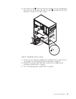
12.
Go to “Completing the parts replacement” on page 61.
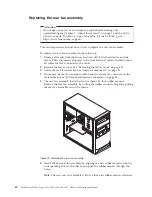
Replacing the power supply assembly
Attention
Do not open your server or attempt any repair before reading and
understanding the Chapter 1, “About this manual,” on page 1 and the
Safety
Information
book. To obtain a copy of the
Safety Information
book, go to:
http://www.lenovo.com/support
This section provides instructions on how to replace the power supply assembly.
To replace the power supply assembly, do the following:
1.
Remove all media from the drives and turn off all attached devices and the
server. Then, disconnect all power cords from electrical outlets and disconnect
all cables that are connected to the server.
2.
Remove the server cover. See “Removing the server cover” on page 33.
3.
Disconnect the power supply assembly cables from the system board and all
drives. See “System-board internal connectors” on page 26.
4.
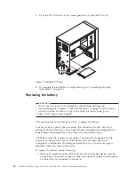
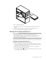
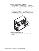
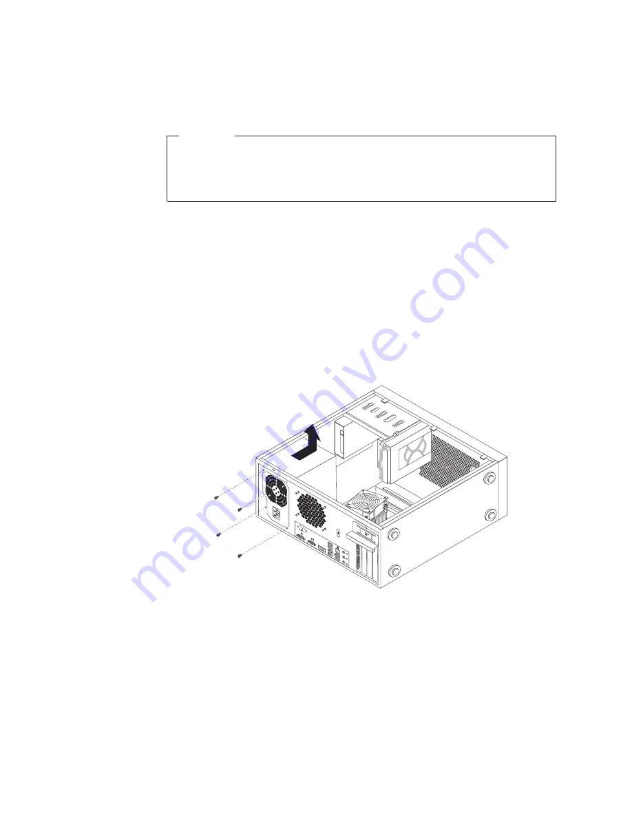
Lay the server on its side and remove the four screws at the rear of the
chassis that secure the power supply assembly.
5.
Slide the power supply assembly to the front of the server and then lift it out
of the chassis.
6.
Ensure that the new power supply assembly is the correct replacement.
7.
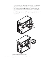
Install the new power supply assembly into the chassis so that the screw holes
in the power supply assembly are aligned with the corresponding holes in the
chassis.
8.
Install and tighten the four screws to secure the new power supply assembly.
Note:
Use only screws provided by Lenovo.
Figure 22. Removing the screws for the power supply assembly
46
ThinkServer TS200v Types 0981, 0992, 1008, and 1010: Hardware Maintenance Manual
Summary of Contents for ThinkServer TS200v
Page 1: ......
Page 2: ......
Page 3: ...ThinkServer TS200v Types 0981 0992 1008 and 1010 Hardware Maintenance Manual ...
Page 28: ...22 ThinkServer TS200v Types 0981 0992 1008 and 1010 Hardware Maintenance Manual ...
Page 34: ...28 ThinkServer TS200v Types 0981 0992 1008 and 1010 Hardware Maintenance Manual ...
Page 84: ...78 ThinkServer TS200v Types 0981 0992 1008 and 1010 Hardware Maintenance Manual ...
Page 107: ......
Page 108: ...Part Number XXXXXX Printed in USA 1P P N XXXXXX ...

