background image

Using passwords

By using the Setup Utility program, you can set passwords to prevent
unauthorized access to your server and data. The following types of passwords are
available:

v

Power-On Password

v

Administrator Password

v

Hard Disk Password

You do not have to set a password to use your server. However, using passwords
improves computing security. If you decide to set a password, read the following
sections.

Password considerations

A password can be any combination of up to 64 alphabetic and numeric characters.
For security reasons, it is recommended to use a strong password that cannot be
easily compromised. To set a strong password, use the following guidelines:

v

Have at least eight characters in length

v

Contain at least one alphabetic character and one numeric character

v

Setup Utility program and hard disk drive passwords are not case sensitive

v

Not be your name or your user name

v

Not be a common word or a common name

v

Be significantly different from your previous passwords

Power-On Password

When a Power-On Password is set, you are prompted to type a valid password
each time the server is turned on. The server cannot be used until the valid
password is typed in.

Administrator Password

Setting an Administrator Password deters unauthorized users from changing
configuration settings. If you are responsible for maintaining the configuration
settings of several servers, you might want to set an Administrator Password.

When an Administrator Password is set, you are prompted to type a valid
password each time you try to access the Setup Utility program. The Setup Utility
program cannot be accessed until a valid password is typed in.

If both the Power-On Password and Administrator Password are set, you can type
either password. However, you must use your Administrator Password to change
any configuration settings.

Hard Disk Password

Setting a Hard Disk Password prevents unauthorized access to the data on the
hard disk drive. When a Hard Disk Password is set, you are prompted to type a
valid password each time you try to access the hard disk drive.

Setting, changing, and deleting a password

To set, change, or delete a password, do the following:

1.

Start the Setup Utility program. See “Starting the Setup Utility program” on
page 79.

2.

From the Setup Utility program main menu, select

Security

.

3.

Depending on the password type, select

Set Power-On Password

,

Set

Administrator Password

, or

Hard Disk Security

Hard Disk Password

.

80

ThinkServer TS200v Types 0981, 0992, 1008, and 1010: Hardware Maintenance Manual

Summary of Contents for ThinkServer TS200v

Page 1: ......

Page 2: ......

Page 3: ...ThinkServer TS200v Types 0981 0992 1008 and 1010 Hardware Maintenance Manual ...

Page 4: ...en developed exclusively at private expense and are sold to governmental entities as commercial items as defined by 48 C F R 2 101 with limited and restricted rights to use reproduction and disclosure LIMITED AND RESTRICTED RIGHTS NOTICE If products data computer software or services are delivered pursuant a General Services Administration GSA contract use reproduction or disclosure is subject to ...

Page 5: ...mbly 46 Replacing the heat sink and fan assembly 47 Replacing the microprocessor 48 Replacing the system board 51 Replacing the primary hard disk drive 53 Replacing the front fan assembly 57 Replacing the rear fan assembly 60 Completing the parts replacement 61 Updating the server configuration 62 Chapter 7 Parts Listing TS200v Machine Types 0981 0992 1008 and 1010 63 Machine Type 0981 63 Machine ...

Page 6: ...olyvinyl Chloride PVC cable and cord notice 96 Turkish statement of compliance 96 Waste electrical and electronic equipment WEEE notices 96 European Union EU WEEE statement 97 Japanese recycling statement 97 Collecting and recycling a disused Lenovo computer or monitor 97 Disposing of Lenovo computer components 97 Disposing of disused lithium batteries from Lenovo computers 98 Index 99 iv ThinkSer...

Page 7: ...cument is available at http www lenovo com support Before servicing a Lenovo product be sure to read the Safety Information See Important Safety Information For information about the terms of the warranty and getting service and assistance see the Warranty and Support Information document Important Safety Information Be sure to read all caution and danger statements in this book before performing ...

Page 8: ...statement is labeled Statement 1 translations for that caution statement are in the Safety Information document under Statement 1 Be sure to read all caution and danger statements in this document before you perform the procedures Read any additional safety information that comes with the server or optional device before you install the device Attention Use No 26 AWG or larger UL listed or CSA cer...

Page 9: ...when there is evidence of fire water or structural damage v Disconnect the attached power cords telecommunications systems networks and modems before you open the device covers unless instructed otherwise in the installation and configuration procedures v Connect and disconnect cables as described in the following table when installing moving or opening covers on this product or attached devices T...

Page 10: ...with the same module type made by the same manufacturer The battery contains lithium and can explode if not properly used handled or disposed of Do not v Throw or immerse into water v Heat to more than 100 C 212 F v Repair or disassemble Dispose of the battery as required by local ordinances or regulations 4 ThinkServer TS200v Types 0981 0992 1008 and 1010 Hardware Maintenance Manual ...

Page 11: ... v Use of controls or adjustments or performance of procedures other than those specified herein might result in hazardous radiation exposure DANGER Some laser products contain an embedded Class 3A or Class 3B laser diode Note the following Laser radiation when open Do not stare into the beam do not view directly with optical instruments and avoid direct exposure to the beam Class 1 Laser Product ...

Page 12: ... and the power switch on the power supply do not turn off the electrical current supplied to the device The device also might have more than one power cord To remove all electrical current from the device ensure that all power cords are disconnected from the power source 1 2 6 ThinkServer TS200v Types 0981 0992 1008 and 1010 Hardware Maintenance Manual ...

Page 13: ...ce devices according to Clause 2 of the German Ordinance for Work with Visual Display Units Important information about replacing RoHS compliant FRUs RoHS The Restriction of Hazardous Substances in Electrical and Electronic Equipment Directive 2002 95 EC is a European Union legal requirement affecting the global electronics industry RoHS requirements must be implemented on Lenovo products placed o...

Page 14: ...must always be replaced using RoHS compliant FRUs so only the FRUs identified as compliant in the system hardware maintenance manual or direct substitutions for those FRUs can be used Products marketed before June 2006 Products marketed after June 2006 Current or original part Replacement FRU Current or original part Replacement FRU Non RoHS Can be Non RoHS Must be RoHS Must be RoHS Non RoHS Can b...

Page 15: ...One PCI Express x1 card slot v One PCI Express x16 card slot System management features v Ability to store power on self test POST hardware test results v Automatic power on startup v Intel Active Management Technology AMT v Intel Hyper Threading technology some models v Intel Rapid Storage Technology RST v Preboot Execution Environment PXE v System Management SM UEFI and SM software v Wake on LAN...

Page 16: ...0 V ac Input frequency range 50 to 60 Hz Voltage selection switch setting 230 V ac Software Lenovo provides software to help get your server up and running EasyStartup The ThinkServer EasyStartup program simplifies the process of installing supported Microsoft Windows operating systems and device drivers on your server The EasyStartup program is provided with your server on DVD The DVD is self sta...

Page 17: ...sten for beep codes v Look for readable instructions or a main menu on the display If you did not receive the correct response proceed to step 6 If you do receive the correct response proceed to step 7 6 Look at the following conditions and follow the instructions v If you hear beep codes during POST go to Beep symptoms on page 17 v If the server displays a POST error go to POST error codes on pag...

Page 18: ... if they 1 Are the exact machine type and models 2 Have the same BIOS level 3 Have the same adapters attachments in the same locations 4 Have the same address jumpers terminators cabling 5 Have the same software versions and levels 6 Have the same diagnostic diskettes version 7 Have the same configuration options set in the system 8 Have the same setup for operating system controlled files Compari...

Page 19: ... on how to create a diagnostic disc To create a diagnostic disc do the following 1 Download a self starting bootable CD DVD image known as an ISO image of the diagnostic program from http www lenovo com support 2 Use any CD DVD burning software to create a diagnostic disc with the ISO image Running the diagnostic program from a diagnostic disc This section provides instructions on how to run the d...

Page 20: ...ment keys highlight a single test within a test category and then press Enter This runs only that test Press Esc at any time to stop the testing process Test results N A PASSED FAILED ABORTED are displayed in the field beside the test description and in the test log See Viewing the test log on page 15 To select one or more tests do the following 1 Open the corresponding test category 2 Using the c...

Page 21: ...er that this is a non recoverable process Full Erase Hard Drive provides a DOS utility that performs the following v Performs all the steps in Quick Erase v Provides a DOS utility that writes random data to all sectors of the hard disk drive v Provides an estimate of time to completion along with a visual representation of completion status v Provides messages that warn the user about a non recove...

Page 22: ...nfiguration Check the configuration and ensure the start up drive is in the boot sequence No operating system installed on the boot drive Install an operating system on the boot drive The boot sector on the start up drive is corrupted The drive must be formatted Do the following 1 Attempt to back up the data on the failing hard disk drive 2 Using the operating system programs format the hard disk ...

Page 23: ...is properly connected to the computer 2 Replace the video adapter card if present 3 Replace the system board 1 long and 3 short beeps Keyboard error Perform the following actions in order 1 Make sure the keyboard is properly connected to the keyboard connector 2 Replace the keyboard 3 Replace the system board 1 long and 9 short beeps BIOS ROM error Perform the following actions in order 1 Start th...

Page 24: ... has become corrupt due to a weak CMOS battery CPU at nnnn nnnn is the running speed of the microprocessor Press Esc to skip memory test Pressing Esc skips the full memory test HARD DISK INSTALL FAILURE Cannot find or initialize the hard disk drive controller or the drive Make sure the hard disk drive is correctly installed If no hard disk drives are installed make sure the hard disk drive selecti...

Page 25: ...has a startable bootable DVD drive v If the startup boot sequence settings have been changed make sure the DVD drive is first in the startup sequence v If more than one DVD drive is installed make sure that only one DVD drive is set as the primary drive Start the EasyStartup DVD from the primary DVD drive The operating system installation program continuously loops Make more space available on the...

Page 26: ... Primary Hard Disk Drive 3 Hard Disk Drive Cable Incorrect memory size during POST 1 Run the Memory tests 2 Memory Module 3 System Board Insert a Diskette icon appears with a known good diagnostics diskette in the first 3 5 inch diskette drive 1 System Board 2 Diskette Drive Cable 3 Network Adapter Intensity or color varies from left to right of characters and color bars 1 Display 2 Video adapter ...

Page 27: ...ice 3 Cable 4 System Board Serial or parallel port device failure adapter port 1 External Device Self Test OK 2 External Device 3 Cable 4 Alternate Adapter 5 System Board Some or all keys on the keyboard do not work 1 Keyboard 2 Keyboard Cable 3 System Board Undetermined problems This section provides instructions on how to find out the failing devices or adapters 1 Turn off the server 2 Remove or...

Page 28: ...22 ThinkServer TS200v Types 0981 0992 1008 and 1010 Hardware Maintenance Manual ...

Page 29: ...and connectors on the front of your server 1 Hard disk drive activity LED 3 Power switch 2 Power on LED 4 USB connectors 2 Rear view Figure 2 on page 24 shows the locations of the connectors on the rear of your server Some connectors on the rear of your server are color coded to help you determine where to connect the cables in your server Figure 1 Front control and connector locations Copyright L...

Page 30: ...onitor connector 9 Audio line in connector 4 DisplayPort connector 10 PCI Express x16 card slot 5 USB connectors 6 11 PCI Express x1 card slot 6 Ethernet connector 12 PCI card slots 2 Figure 2 Rear connector locations 24 ThinkServer TS200v Types 0981 0992 1008 and 1010 Hardware Maintenance Manual ...

Page 31: ...s that use a DisplayPort connector Ethernet connector Used to attach an Ethernet cable for a local area network LAN Note To operate the server within FCC Class B limits use a Category 5 Ethernet cable Microphone connector Used to attach a microphone to your server when you want to record sound or if you use speech recognition software Serial port Used to attach an external modem a serial printer o...

Page 32: ...SB connectors 2 6 DIMM 4 16 PCI card slots 2 7 DIMM 3 17 PCI Express x1 card slot 8 Thermal sensor connector 18 PCI Express x16 card slot 9 24 pin power connector 19 System fan connector 10 SATA connectors 3 20 Battery Internal components Figure 4 on page 27 shows the locations of the various components in your server To remove the server cover and access to the inside of the server see Removing t...

Page 33: ...ome models 2 Microprocessor8 8 Primary hard disk drive 3 Memory modules 9 System board 4 Optical drive 10 Rear fan assembly 5 Front bezel 11 Power supply 6 Front fan assembly Figure 4 Component locations Chapter 5 Locating Server Controls and connectors 27 ...

Page 34: ...28 ThinkServer TS200v Types 0981 0992 1008 and 1010 Hardware Maintenance Manual ...

Page 35: ... those items Use good judgment to identify potential unsafe conditions that might be caused by non Lenovo alterations or attachment of non Lenovo features or options that are not addressed in this section If you identify an unsafe condition you must determine how serious the hazard is and whether you must correct the problem before you work on the product Consider the following conditions and the ...

Page 36: ... voltages v Locate the emergency power off EPO switch disconnecting switch or electrical outlet so that you can turn off the power quickly in the event of an electrical accident v Disconnect all power before you perform a mechanical inspection work near power supplies or remove or install main units v Before you work on the equipment disconnect the power cord If you cannot disconnect the power cor...

Page 37: ...or other grounding system when working inside the server with the power on v Handle the device carefully holding it by its edges or its frame v Do not touch solder joints pins or exposed circuitry v Do not leave the device where others can handle and damage it v While the device is still in its static protective package touch it to an unpainted metal part on the outside of the server for at least ...

Page 38: ...s of your server and maintain your server by installing or replacing hardware Attention Do not open your server or attempt any repair before reading and understanding the Chapter 1 About this manual on page 1 and the Safety Information book To obtain a copy of the Safety Information book go to http www lenovo com support Notes 1 Use only server parts provided by Lenovo 2 When installing or replaci...

Page 39: ...e minutes to let the server cool before removing the server cover To remove the server cover do the following 1 Remove any media from the drives and turn off all attached devices and the server 2 Disconnect all power cords from electrical outlets 3 Disconnect the power cords Input Output I O cables and any other cables that are connected to the server See Front view on page 23 and Rear view on pag...

Page 40: ...on provides instructions on how to remove and reinstall the front bezel To remove and reinstall the front bezel do the following 1 Remove all media from the drives and turn off all attached devices and the server Then disconnect all power cords from electrical outlets and disconnect all cables that are connected to the server 2 Remove the server cover See Removing the server cover on page 33 3 Rem...

Page 41: ...nformation book To obtain a copy of the Safety Information book go to http www lenovo com support This section provides instructions on how to install or replace a PCI card Your server has two standard PCI card slots one PCI Express x1 card slot and one PCI Express x16 card slot To install or replace a PCI card do the following 1 Remove all media from the drives and turn off all attached devices a...

Page 42: ...3 At the rear of the server press the release button 1 to open the PCI card latch 2 Figure 7 Opening the PCI card latch 36 ThinkServer TS200v Types 0981 0992 1008 and 1010 Hardware Maintenance Manual ...

Page 43: ...ving each side of the PCI card a small amount until it is removed from the card slot 5 Remove the new PCI card from its static protective package 6 Install the new PCI card into the appropriate slot on the system board See System board internal connectors on page 26 Note If you are installing a PCI Express x16 card make sure the memory slot retaining clips are closed before you install the PCI Exp...

Page 44: ...time and settings for built in features such as parallel port assignments configuration A battery keeps this information active when you turn off the server The battery normally requires no charging or maintenance throughout its life however no battery lasts forever If the battery fails the date time and configuration information including passwords are lost An error message is displayed when you ...

Page 45: ...r replacing the battery 10 Use the Setup Utility program to set the date time and any passwords See Chapter 8 Configuring the server on page 79 Installing or replacing a memory module Attention Do not open your server or attempt any repair before reading and understanding the Chapter 1 About this manual on page 1 and the Safety Information book To obtain a copy of the Safety Information book go to...

Page 46: ...for easier access to the system board 4 Locate the memory slots See System board internal connectors on page 26 5 Remove any parts that might prevent your access to the memory slots Note Depending on your server model you might need to remove the PCI Express x16 card for easier access to the memory slots See Installing or replacing a PCI card on page 35 6 If you are installing a new memory module ...

Page 47: ... following 1 Remove all media from the drives and turn off all attached devices and the server Then disconnect all power cords from electrical outlets and disconnect all cables that are connected to the server 2 Remove the server cover See Removing the server cover on page 33 3 Remove the front bezel See Removing and reinstalling the front bezel on page 34 4 Depending on whether you are installing...

Page 48: ...he new optical drive into the optical drive bay from the front of the server until the optical drive snaps into position Figure 15 Removing the optical drive Figure 16 Installing the optical drive retainer 42 ThinkServer TS200v Types 0981 0992 1008 and 1010 Hardware Maintenance Manual ...

Page 49: ...com support This section provides instructions on how to replace the secondary hard disk drive Installing a secondary hard disk drive To install a secondary hard disk drive do the following 1 Remove all media from the drives and turn off all attached devices and the server Then disconnect all power cords from electrical outlets and disconnect all cables that are connected to the server 2 Remove th...

Page 50: ...d disk drive Do not touch the circuit board 5 on the bottom of the hard disk drive Note If you are installing a 2 5 inch hard disk drive install the hard disk drive into a 2 5 inch to 3 5 inch hard disk drive tray first and then install the tray into the blue bracket 8 Slide the new hard disk drive with the blue bracket into the secondary hard disk drive cage until it snaps into position Figure 18...

Page 51: ...the hard disk drive cage downward until it snaps into position Make sure that the hard disk drive cage is secured in the chassis 11 Reconnect the signal cable and power cable of the secondary hard disk drive Figure 20 Installing the secondary hard disk drive Figure 21 Installing the secondary hard disk drive Chapter 6 Replacing FRUs 45 ...

Page 52: ...over See Removing the server cover on page 33 3 Disconnect the power supply assembly cables from the system board and all drives See System board internal connectors on page 26 4 Lay the server on its side and remove the four screws at the rear of the chassis that secure the power supply assembly 5 Slide the power supply assembly to the front of the server and then lift it out of the chassis 6 Ens...

Page 53: ... turn off all attached devices and the server Then disconnect all power cords from electrical outlets and disconnect all cables that are connected to the server 2 Remove the server cover See Removing the server cover on page 33 3 Lay the server on its side for easier access to the system board 4 Locate the heat sink and fan assembly See System board internal connectors on page 26 5 Disconnect the ...

Page 54: ...cure the heat sink and fan assembly as shown in Figure 23 a Partially tighten screw 1 then fully tighten screw 2 and then fully tighten screw 1 b Partially tighten screw 3 then fully tighten screw 4 and then fully tighten screw 3 10 Connect the heat sink and fan assembly cable to the microprocessor fan connector on the system board See System board internal connectors on page 26 11 Go to Completin...

Page 55: ...over on page 33 3 Lay the server on its side to get easier access to the system board 4 Remove the heat sink and fan assembly from the system board See Replacing the heat sink and fan assembly on page 47 5 Lift the small handle 1 and open the retainer 2 to access the microprocessor 3 6 Lift the microprocessor straight up and out of the socket Notes a Your microprocessor and socket might look diffe...

Page 56: ...orner of the new microprocessor with the corresponding beveled corner of the microprocessor socket 9 Lower the new microprocessor straight down into the microprocessor socket on the system board 10 Close the microprocessor retainer and lock it into position with the small handle to secure the new microprocessor in the socket 11 Reinstall the heat sink and fan assembly See Replacing the heat sink a...

Page 57: ...ical outlets and disconnect all cables that are connected to the server 2 Remove the server cover See Removing the server cover on page 33 3 Lay the server on its side for easier access to the system board 4 Remove all memory modules and PCI cards that are currently installed See Installing or replacing a memory module on page 39 and Installing or replacing a PCI card on page 35 5 Remove the secon...

Page 58: ...eplacing the secondary hard disk drive on page 43 16 Connect all cables to the system board See System board internal connectors on page 26 17 Go to Completing the parts replacement on page 61 The failing system board must be returned with a microprocessor socket cover to protect the pins during shipping and handling To install the microprocessor socket cover 1 Remove the microprocessor from the m...

Page 59: ... and then lower the lever to secure the retainer Make sure the lever is locked into position Replacing the primary hard disk drive Attention Do not open your server or attempt any repair before reading and understanding the Chapter 1 About this manual on page 1 and the Safety Information book To obtain a copy of the Safety Information book go to http www lenovo com support This section provides in...

Page 60: ...sconnect the signal cable and the power cable from the rear of the hard disk drive 5 Press the blue release tab 1 downward slide the hard disk drive cage 2 to the rear of the server and then pivot it outward to completely remove the drive cage from the chassis Then pull on the blue handle 3 to release and remove the hard disk drive from the drive cage 6 Flex the sides of the blue bracket to remove...

Page 61: ...board 5 on the bottom of the hard disk drive Note If you are installing a 2 5 inch hard disk drive install the hard disk drive into a 2 5 inch to 3 5 inch hard disk drive tray first and then install the tray into the blue bracket 8 Slide the new hard disk drive with the blue bracket into the drive cage until it snaps into position Figure 29 Installing the hard disk drive into the bracket Chapter 6...

Page 62: ... hard disk drive cage into place Then slide the drive cage to the front of the server until it snaps into position Note There are two arrows one on the upper drive cage and one on the hard disk drive cage The arrows are aligned when the hard disk drive is in the proper position Figure 30 Installing the primary hard disk drive 56 ThinkServer TS200v Types 0981 0992 1008 and 1010 Hardware Maintenance...

Page 63: ...the front fan assembly do the following 1 Remove all media from the drives and turn off all attached devices and the server Then disconnect all power cords from electrical outlets and disconnect all cables that are connected to the server 2 Remove the server cover See Removing the server cover on page 33 3 Remove the front bezel See Removing and reinstalling the front bezel on page 34 4 Disconnect...

Page 64: ...h the front fan assembly to the chassis as shown and then completely remove the front fan assembly from the chassis Figure 31 Removing the front fan assembly 58 ThinkServer TS200v Types 0981 0992 1008 and 1010 Hardware Maintenance Manual ...

Page 65: ...ured in place 7 Connect the new front fan assembly cable to the power fan connector on the system board See System board internal connectors on page 26 8 Reinstall the secondary hard disk drive if removed See Replacing the secondary hard disk drive on page 43 9 Go to Completing the parts replacement on page 61 Figure 32 Installing the front fan assembly Chapter 6 Replacing FRUs 59 ...

Page 66: ...ve the server cover See Removing the server cover on page 33 3 Locate the rear fan assembly See Internal components on page 26 4 Disconnect the rear fan assembly cable from the system fan connector on the system board See System board internal connectors on page 26 5 The rear fan assembly is attached to the chassis by four rubber mounts Remove the rear fan assembly by cutting the rubber mounts and...

Page 67: ...ssembled correctly and that no tools or loose screws are left inside your server See Internal components on page 26 for the locations of various components in your server 2 If you have removed the front bezel reinstall it See Removing and reinstalling the front bezel on page 34 3 Make sure that the cables are routed correctly before reinstalling the server cover Keep cables clear of the hinges and...

Page 68: ... Updating the server configuration When you start the server for the first time after you install or remove an internal option or external device you might receive a message that the configuration has changed The Setup Utility program starts automatically so that you can save the new configuration settings Some options have device drivers that you must install For information about installing devi...

Page 69: ...ervice customer replaceable unit You may install an optional service CRU yourself or request Lenovo to install it at no additional charge under the type of warranty service that is designated for your server v Field replaceable unit FRU FRUs must be installed only by trained service technicians For information about the terms of the warranty and getting service and assistance see the Warranty and ...

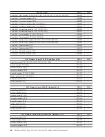
Page 70: ...CTO All Models 45K2306 N 7 Hard disk drive 250GB SATA Enterprise 7200 rpm 3 Gb s 8MB cache 3 5 models CTO 11U 11F 11S 11L 11D 11Y 11G 11M 12U 12F 12S 12L 12D 12Y 12G 12M 13U 13F 13S 13L 13D 13Y 13G 13M 46U3100 1 7 Hard disk drive 500GB SATA Enterprise 7200 rpm 3 Gb s 16MB cache 3 5 models CTO 46U3101 1 7 Hard disk drive 1TB SATA Enterprise 7200 rpm 3 Gb s 32MB cache 3 5 models CTO 46U3103 1 8 Syst...

Page 71: ...CTO 67Y1425 1 0981 Line Cords FRU CRU Line Cord US models CTO 11U 12U 13U 11F 12F 13F 11S 12S 13S 11L 12L 13L 11D 12D 13D 41R3184 1 Line Cord US models CTO 11U 12U 13U 11F 12F 13F 11S 12S 13S 11L 12L 13L 11D 12D 13D 41R3185 1 Line Cord China models CTO 41R3256 1 Line Cord China models CTO 41R3257 1 Line Cord Japan models CTO 41R3248 1 Line Cord Japan models CTO 41R3249 1 Line Cord Brazil models CT...

Page 72: ...ls CTO 43N9029 1 Line Cord Thailand models CTO 43N9030 1 0981 Windows Server 2008 R2 Foundation 64 bit FRU CRU English models CTO 13U 13F 13S 13L 13D 13Y 13G 13M 90Y1166 1 French models CTO 13F 90Y1168 1 German models CTO 90Y1169 1 Japanese models CTO 90Y1171 1 Spanish models CTO 13S 13D13Y 90Y1172 1 Italian models CTO 13S 13L13Y 90Y1170 1 Turkish models CTO 90Y1173 1 Dutch models CTO 90Y1167 1 09...

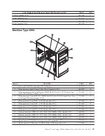
Page 73: ...Thread Dual Core iGfx Speed 733MHz models CTO 71Y6960 N 2 Microprocessor Core i3 540 2 93GHz models CTO 71Y5304 N 2 Microprocessor Core i5 650 3 20GHz models CTO 71Y6961 N 2 Microprocessor Core i5 660 3 33GHz models CTO 71Y6962 N 2 Microprocessor Core i5 670 3 46GHz models CTO 71Y6963 N 3 Memory modules DDR3 ECC PC3 10600 1GB UDIMM 1333 models CTO 46R6026 1 3 Memory modules DDR3 ECC PC3 10600 2GB ...

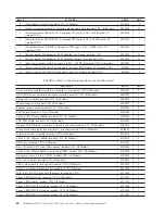
Page 74: ...TO All Models 45K2307 2 Speaker cable 400mm models CTO All Models 43N9091 2 EMC Shield models CTO All Models 41N8080 2 Cable SATA 457mm RoHS models CTO All Models 43N9013 2 FDD EMI shield models CTO All Models 41N8078 2 Optional HDD bracket assembly without 4 pin cable models CTO All Models 41R6106 1 Temp sense cable 6pin 460 mm kit w bracket models CTO All Models 45J9495 2 Intrusion switch assemb...

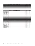
Page 75: ...ng models CTO 41R3225 1 Line Cord Taiwan models CTO 41R3278 1 Line Cord Taiwan models CTO 41R3279 1 Line Cord Italy models CTO 41R3232 1 Line Cord Italy models CTO 41R3233 1 Line Cord A models models CTO 41R3208 1 Line Cord A models models CTO 41R3209 1 Line Cord Denmark models CTO 41R3212 1 Line Cord Denmark models CTO 41R3213 1 Line Cord Switzerland models CTO 41R3228 1 Line Cord Switzerland mod...

Page 76: ... 90Y1185 1 Japanese models CTO 90Y1186 1 Spanish models CTO 90Y1187 1 Italian models CTO 90Y1188 1 Turkish models CTO 90Y1189 1 Dutch models CTO 90Y1190 1 0992 Windows Small Business Server 2008 Standard w SP2 FRU CRU English models CTO 90Y1174 1 French models CTO 90Y1176 1 German models CTO 90Y1177 1 Japanese models CTO 90Y1179 1 Spanish models CTO 90Y1180 1 Italian models CTO 90Y1178 1 Turkish m...

Page 77: ... modules DDR3 ECC PC3 10600 1GB UDIMM 1333 models CTO 46R6026 1 3 Memory modules DDR3 ECC PC3 10600 2GB UDIMM 1333 models CTO 46R6027 1 3 Memory modules DDR3 ECC PC3 10600 4GB UDIMM 1333 models CTO 64Y9570 1 4 Optical drive DVD ROM Drive 16x 48x SATA models CTO 71Y5543 1 4 Optical drive DVD Burner CD RW Rambo 8 SATA models CTO 71Y5545 1 5 Front Bezel assembly models CTO All Models 90Y0051 2 6 Fron...

Page 78: ...nse cable 6pin 460 mm kit w bracket models CTO All Models 45J9495 2 Intrusion switch assembly models CTO All Models 41R6116 2 Cable SATA 250mm RoHS models CTO All Models 43N9012 2 HDD tray models CTO All Models 41R6291 1 Rear IO shield ATX with USB number models CTO All Models 43N9846 2 Cable SATA 120mm RoHS used for 2nd HDD models CTO All Models 41R3328 2 Adapter bracket 2 5 to 3 5 HDD models CTO...

Page 79: ...O 41R3233 1 Line Cord A models models CTO 41R3208 1 Line Cord A models models CTO 41R3209 1 Line Cord Denmark models CTO 41R3212 1 Line Cord Denmark models CTO 41R3213 1 Line Cord Switzerland models CTO 41R3228 1 Line Cord Switzerland models CTO 41R3229 1 Line Cord Israel models CTO 41R3236 1 Line Cord Israel models CTO 41R3237 1 Line Cord South Africa models CTO 41R3220 1 Line Cord South Africa m...

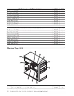
Page 80: ...Y1190 1 1008 Windows Small Business Server 2008 Standard w SP2 FRU CRU English models CTO 90Y1174 1 French models CTO 90Y1176 1 German models CTO 90Y1177 1 Japanese models CTO 90Y1179 1 Spanish models CTO 90Y1180 1 Italian models CTO 90Y1178 1 Turkish models CTO 90Y1181 1 Dutch models CTO 90Y1175 1 Machine Type 1010 Item 1010 FRUs FRU CRU 1 Heat sink 73 95 Watt models CTO All Models 43N9700 N 74 T...

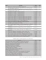
Page 81: ...s 16MB cache 3 5 models CTO 46U3101 1 7 Hard disk drive 1TB SATA Enterprise 7200 rpm 3 Gb s 32MB cache 3 5 models CTO 46U3103 1 8 System board Motherboard TPM Enabled not Russia models CTO 64Y8423 N 8 System board Motherboard TPM Disabled Russia Only models CTO 64Y8424 N 9 Rear fan assembly with Fan Grill 0 to 20 750 RPM models CTO All Models 45K2324 2 10 Power supply 280 Watt Power Supply 85 plus...

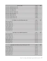
Page 82: ...85 1 Line Cord China models CTO 41R3256 1 Line Cord China models CTO 41R3257 1 Line Cord Japan models CTO 41R3248 1 Line Cord Japan models CTO 41R3249 1 Line Cord Brazil models CTO 41R3270 1 Line Cord Brazil models CTO 41R3271 1 Line Cord LA High Volt APU models CTO 41R3176 1 Line Cord LA High Volt APU models CTO 41R3177 1 Line Cord Australia New Zealand models CTO 41R3196 1 Line Cord Australia Ne...

Page 83: ...odels CTO 90Y1171 1 Spanish models CTO 90Y1172 1 Italian models CTO 90Y1170 1 Turkish models CTO 90Y1173 1 Dutch models CTO 90Y1167 1 1010 Windows Server 2008 R2 Standard 64 bit FRU CRU English models CTO 90Y1183 1 French models CTO 90Y1184 1 German models CTO 90Y1185 1 Japanese models CTO 90Y1186 1 Spanish models CTO 90Y1187 1 Italian models CTO 90Y1188 1 Turkish models CTO 90Y1189 1 Dutch models...

Page 84: ...78 ThinkServer TS200v Types 0981 0992 1008 and 1010 Hardware Maintenance Manual ...

Page 85: ...anced settings on page 82 v Exiting from the Setup Utility program on page 82 Starting the Setup Utility program To start the Setup Utility program do the following 1 Make sure your server is turned off 2 Repeatedly press and release the F1 key when turning on the server When you hear multiple beeps or see a logo screen release the F1 key Note If a Power On Password or an Administrator Password ha...

Page 86: ...lid password is typed in Administrator Password Setting an Administrator Password deters unauthorized users from changing configuration settings If you are responsible for maintaining the configuration settings of several servers you might want to set an Administrator Password When an Administrator Password is set you are prompted to type a valid password each time you try to access the Setup Util...

Page 87: ... 3 Depending on the device you want to enable or disable do one of the following v Select USB Setup to enable or disable a USB device v Select ATA Drives Setup to enable or disable an internal or external SATA device 4 Select the desired settings and press Enter 5 Press F10 to save and exit the Setup Utility program See Exiting from the Setup Utility program on page 82 Selecting a startup device I...

Page 88: ...bled your server performance might be degraded Therefore you should always set HyperThreading to Disabled unless you are sure your operating system supports HyperThreading Exiting from the Setup Utility program After you finish viewing or changing settings press Esc to return to the Setup Utility program main menu You might have to press Esc several times Then do one of the following v If you want...

Page 89: ... and press Enter 5 Press F10 to save the new settings and exit the Setup Utility program See Exiting from the Setup Utility program on page 82 Creating RAID volumes This section describes how to use the Intel Matrix Storage Manager option ROM configuration utility to create RAID volumes To create RAID volumes do the following 1 Press Ctrl I when prompted to enter the Intel Matrix Storage Manager o...

Page 90: ...he Reset Disks to Non RAID function you can Return to step 2 to delete additional RAID volumes See Creating RAID volumes on page 83 for RAID volume creation Use the up and down arrow keys to select Exit and press Enter Updating system programs This section contains information about updating the POST UEFI and recovering from a POST UEFI update failure This section provides information about the fo...

Page 91: ...ce window displays release the F12 key 3 Select the optical drive of your choice as the first boot device 4 Insert the disc into the optical drive and press Enter The update begins 5 When prompted to change the serial number press N Note If you want to change the serial number press Y when prompted Type in the serial number and then press Enter 6 When prompted to change the machine type model pres...

Page 92: ...reconnect the power cords for the server and monitor to electrical outlets See Completing the parts replacement on page 61 8 Repeatedly press and release the F12 key when turning on the server When the Please select boot device window displays release the F12 key 9 Select the optical drive of your choice as the first boot device 10 Insert the POST UEFI update flash disc into the optical drive and ...

Page 93: ...gured as your first device in the startup sequence Use the Setup Utility program to view or change your startup sequence See Viewing or changing the startup device sequence on page 82 4 To install an operating system you need the operating system installation disc CD or DVD and the associated product key if one was provided To start the ThinkServer EasyStartup DVD do the following 1 Insert the Thi...

Page 94: ...e the procedure Installing ThinkServer EasyManage Agent To install the ThinkServer EasyManage Agent you must already have a core server running the ThinkServer EasyManage Core Server program The ThinkServer EasyManage Agent must be installed from that core server Refer to the ThinkServer EasyManage Core Server documentation about Agent deployment for instructions on the various ways to deploy the ...

Page 95: ...information could include technical inaccuracies or typographical errors Changes are periodically made to the information herein these changes will be incorporated in new editions of the publication Lenovo may make improvements and or changes in the product s and or the program s described in this publication at any time without notice The products described in this document are not intended for u...

Page 96: ...otected by method claims of certain U S patents and other intellectual property rights owned by Macrovision Corporation and other rights owners Use of this copyright protection technology must be authorized by Macrovision Corporation and is intended for home and other limited viewing uses only unless otherwise authorized by Macrovision Corporation Reverse engineering or disassembly is prohibited E...

Page 97: ...ate the receiving antenna v Increase the separation between the equipment and receiver v Connect the equipment into an outlet on a circuit different from that to which the receiver is connected v Consult an authorized dealer or service representative for help Lenovo is not responsible for any radio or television interference caused by using other than specified or recommended cables or connectors ...

Page 98: ...e B ein Um dieses sicherzustellen sind die Geräte wie in den Handbüchern beschrieben zu installieren und zu betreiben Des Weiteren dürfen auch nur von der Lenovo empfohlene Kabel angeschlossen werden Lenovo übernimmt keine Verantwortung für die Einhaltung der Schutzanforderungen wenn das Produkt ohne Zustimmung der Lenovo verändert bzw wenn Erweiterungskomponenten von Fremdherstellern ohne Empfehl...

Page 99: ...es should not exceed five 5 To be certain of the number of devices you may connect to your line as determined by the REN you should call your local telephone company to determine the maximum REN for your calling area 3 If the device causes harm to the telephone network the telephone company may discontinue your service temporarily If possible they will notify you in advance if advance notice is no...

Page 100: ...uest the user to disconnect the equipment Users should ensure for their own protection that the electrical ground connections of the power utility telephone lines and internal metallic water pipe system if present are connected together This precaution may be particularly important in rural areas CAUTION Users should not attempt to make such connections themselves but should contact the appropriat...

Page 101: ... Thailand Turks and Caicos Islands United States Venezuela Virgin Islands 41R3196 or 41R3197 Australia Fiji Kiribati Nauru New Zealand Papua New Guinea 41R3208 or 41R3209 Afghanistan Albania Algeria Andorra Angola Armenia Austria Azerbaijan Belarus Belgium Benin Bosnia and Herzegovina Bulgaria Burkina Faso Burundi Cambodia Cameroon Cape Verde Central African Republic Chad Comoros Congo Democratic ...

Page 102: ...duct or cords associated with accessories sold with this product will expose you to lead a chemical known to the State of California to cause cancer and birth defects or other reproductive harm Wash hands after handling Turkish statement of compliance The Lenovo product meets the requirements of the Republic of Turkey Directive on the Restriction of the Use of Certain Hazardous Substances in Elect...

Page 103: ...ed Lenovo computer or monitor If you are a company employee and need to dispose of a Lenovo computer or monitor that is the property of the company you must do so in accordance with the Law for Promotion of Effective Utilization of Resources Computers and monitors are categorized as industrial waste and should be properly disposed of by an industrial waste disposal contractor certified by a local ...

Page 104: ...r is off or disconnected from the main power source If you want to replace it with a new one contact your place of purchase or ask for a repair service provided by Lenovo If you have replaced it by yourself and want to dispose of the disused lithium battery insulate it with vinyl tape contact your place of purchase and follow their instructions If you use a Lenovo computer at home and need to disp...

Page 105: ...80 Power On Password 80 setting changing deleting 80 passwords using 80 PCI card 35 installing replacing 35 slots 35 power supply assembly replacing 46 power on self test POST 84 Power On Password 80 problem isolation tables 16 programs updating system 84 R rear connectors 23 rear fan assembly replacing 60 recovering from a POST UEFI update failure 86 recovery boot block 86 removing server cover 3...

Page 106: ...V VGA monitor connector 25 video subsystem 9 viewing and changing settings 79 100 ThinkServer TS200v Types 0981 0992 1008 and 1010 Hardware Maintenance Manual ...

Page 107: ......

Page 108: ...Part Number XXXXXX Printed in USA 1P P N XXXXXX ...

Reviews: