1
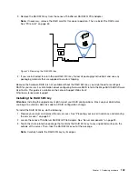
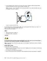
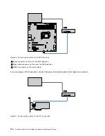
Power connector on the rear of the LTO-6 tape drive
2
Signal cable connector on the rear of the LTO-6 tape drive
3
Mini-SAS signal cable connector on the RAID card
Connecting cables for the non-hot-swap drives
Note:
The server configuration with a non-hot-swap power supply is used as an example. Your server might
come with two hot-swap redundant power supplies and a power distribution board.
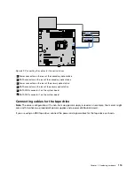
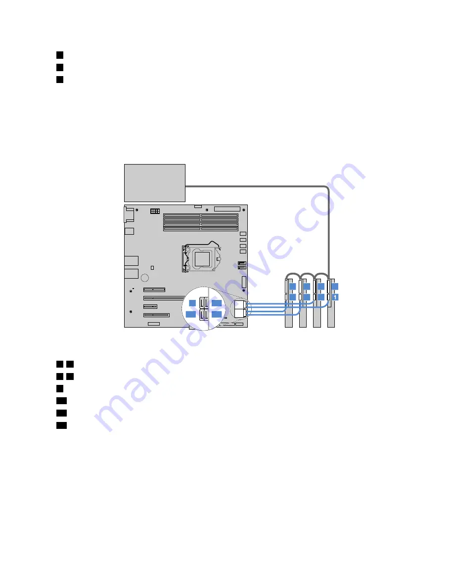
Connect the power and signal cables for the non-hot-swap drives as shown.
2
4
3
6
5
8
7
9
12
10
11
Figure 92. Connecting the power and signal cables
1
–
4
SATA connectors on the rear of the HDDs 0–3
5
–
8
Power connectors on the rear of the HDDs 0–3
9
SATA connector 0 on the system board (connected to HDD 0)
10
SATA connector 1 on the system board (connected to HDD 1)
11
SATA connector 2 on the system board (connected to HDD 2)
12
SATA connector 3 on the system board (connected to HDD 3)
Connecting cables for the backplanes
Depending on whether you are using the Lenovo ThinkServer SAS 12G Expander PCIe Card (hereinafter
referred to as the expander card), refer to one of the following instructions:
•
“For server configurations without an expander card” on page 117
•
“For server configurations with an expander card” on page 120
For server configurations without an expander card
If your server comes with one 3.5-inch-drive backplane, connect the power and signal cables as shown.
117
Summary of Contents for ThinkServer TS460
Page 14: ...xii ThinkServer TS460 User Guide and Hardware Maintenance Manual ...
Page 18: ...4 ThinkServer TS460 User Guide and Hardware Maintenance Manual ...
Page 52: ...38 ThinkServer TS460 User Guide and Hardware Maintenance Manual ...
Page 68: ...54 ThinkServer TS460 User Guide and Hardware Maintenance Manual ...
Page 138: ...124 ThinkServer TS460 User Guide and Hardware Maintenance Manual ...
Page 144: ...130 ThinkServer TS460 User Guide and Hardware Maintenance Manual ...
Page 148: ...134 ThinkServer TS460 User Guide and Hardware Maintenance Manual ...
Page 160: ...146 ThinkServer TS460 User Guide and Hardware Maintenance Manual ...
Page 171: ......
Page 172: ......

