1
2
10
12
13
14
11
3
4
5
7
8
9
6
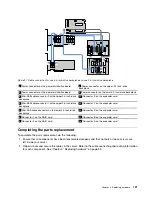
Figure 97. Cable connection for one 3.5-inch-drive backplane and one 2.5-inch-drive backplane
1
Power connector on the power distribution board
3
Power connector on the upper 2.5-inch-drive
backplane
2
Power connector on the power distribution board
6
Power connector on the lower 3.5-inch-drive backplane
4
Mini-SAS cable connector 0 on the upper 2.5-inch-drive
backplane
11
Connector E on the expander card
5
Mini-SAS cable connector 1 on the upper 2.5-inch-drive
backplane
10
Connector F on the expander card
7
Mini-SAS cable connector on the lower 3.5-inch-drive
backplane
12
Connector C on the expander card
8
Connector 1 on the RAID card
13
Connector B on the expander card
9
Connector 0 on the RAID card
14
Connector A on the expander card
Completing the parts replacement
To complete the parts replacement, do the following:
1. Ensure that all components have been reassembled properly and that no tools or loose screws are
left inside your server.
2. Properly route and secure the cables in the server. Refer to the cable connecting and routing information
for each component. See Chapter 5 “Replacing hardware” on page 55.
121
Summary of Contents for ThinkServer TS460
Page 14: ...xii ThinkServer TS460 User Guide and Hardware Maintenance Manual ...
Page 18: ...4 ThinkServer TS460 User Guide and Hardware Maintenance Manual ...
Page 52: ...38 ThinkServer TS460 User Guide and Hardware Maintenance Manual ...
Page 68: ...54 ThinkServer TS460 User Guide and Hardware Maintenance Manual ...
Page 138: ...124 ThinkServer TS460 User Guide and Hardware Maintenance Manual ...
Page 144: ...130 ThinkServer TS460 User Guide and Hardware Maintenance Manual ...
Page 148: ...134 ThinkServer TS460 User Guide and Hardware Maintenance Manual ...
Page 160: ...146 ThinkServer TS460 User Guide and Hardware Maintenance Manual ...
Page 171: ......
Page 172: ......


