1
1
2
2
0
MGMT
3
4
ID
1
3
4
9
5
6
8
7
2
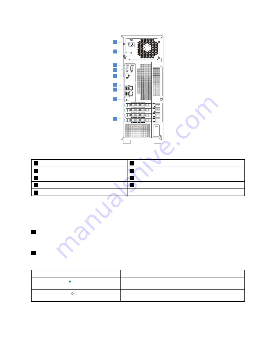
Figure 4. Rear view of the server
1
Power cord connector
2
Power supply status LED
3
VGA connector (DB-15)
4
Serial connector
5
Ethernet connector for system management
6
USB 3.0 connectors (4)
7
Ethernet connectors (RJ-45) (2)
8
System identification button/LED
9
Expansion card area
Your server model might have one or two hot-swap redundant power supplies. Each hot-swap redundant
power supply has one power cord connector on the rear of the server. For each hot-swap redundant power
supply, there might be one or two status LEDs on the power supply near the power cord connector. For
information about the status LEDs, see “Hot-swap power supply status LEDs” on page 26.
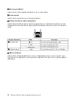
1
Power cord connector
Used to connect the power cord.
2
Power supply status LED
The LED indicates the status of the power supply.
Power supply status LED
Description
Green
The power supply is connected to the ac power source and is
working normally.
Off
The power supply is disconnected from the ac power source or
has failed.
17
Summary of Contents for ThinkServer TS460
Page 14: ...xii ThinkServer TS460 User Guide and Hardware Maintenance Manual ...
Page 18: ...4 ThinkServer TS460 User Guide and Hardware Maintenance Manual ...
Page 52: ...38 ThinkServer TS460 User Guide and Hardware Maintenance Manual ...
Page 68: ...54 ThinkServer TS460 User Guide and Hardware Maintenance Manual ...
Page 138: ...124 ThinkServer TS460 User Guide and Hardware Maintenance Manual ...
Page 144: ...130 ThinkServer TS460 User Guide and Hardware Maintenance Manual ...
Page 148: ...134 ThinkServer TS460 User Guide and Hardware Maintenance Manual ...
Page 160: ...146 ThinkServer TS460 User Guide and Hardware Maintenance Manual ...
Page 171: ......
Page 172: ......

