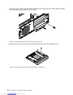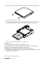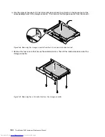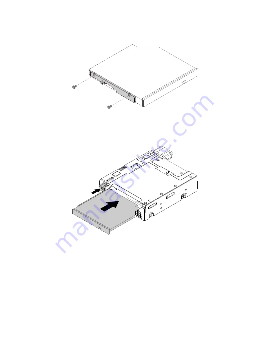
3. Install the two screws to secure the slim optical drive retainer to the side of the new slim optical drive.
Figure 158. Installing the slim optical drive retainer
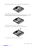
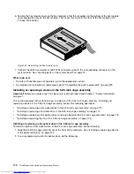
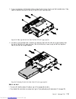
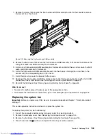
4. Install the slim optical drive with the retainer into the 5.25-inch cage assembly. Press the tab at the front
of the 5.25-inch cage assembly until you hear a click. The slim optical drive is secured in place.
Figure 159. Installing the slim optical drive in the 5.25-inch cage assembly
What to do next:
• To work with another piece of hardware, go to the appropriate section.
• To complete the installation or replacement, go to “Completing the parts replacement” on page 223.
Installing or replacing a hard disk drive in the 5.25-inch cage assembly
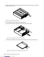
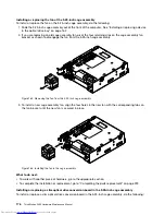
To install or replace a slim optical drive in the 5.25-inch cage assembly, do the following:
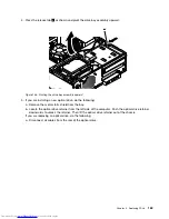
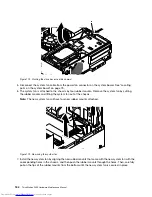
1. Slide the 5.25-inch cage assembly out of the front of the computer. See “Installing or replacing a device
in the optical drive bay” on page 162.
174
ThinkStation P300 Hardware Maintenance Manual
Summary of Contents for ThinkStation P300
Page 1: ...ThinkStation P300 Hardware Maintenance Manual Machine Types 30AG 30AH 30AJ and 30AK ...
Page 6: ......
Page 13: ...Chapter 1 Safety information 7 ...
Page 17: ...Chapter 1 Safety information 11 ...
Page 18: ...1 2 12 ThinkStation P300 Hardware Maintenance Manual ...
Page 19: ...1 2 Chapter 1 Safety information 13 ...
Page 24: ...1 2 18 ThinkStation P300 Hardware Maintenance Manual ...
Page 25: ...1 2 Chapter 1 Safety information 19 ...
Page 28: ...22 ThinkStation P300 Hardware Maintenance Manual ...
Page 32: ...26 ThinkStation P300 Hardware Maintenance Manual ...
Page 72: ...66 ThinkStation P300 Hardware Maintenance Manual ...
Page 76: ...Figure 3 Locating major FRUs and CRUs 70 ThinkStation P300 Hardware Maintenance Manual ...
Page 88: ...82 ThinkStation P300 Hardware Maintenance Manual ...
Page 236: ...230 ThinkStation P300 Hardware Maintenance Manual ...
Page 242: ...236 ThinkStation P300 Hardware Maintenance Manual ...
Page 243: ......
Page 244: ......

