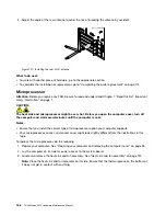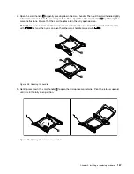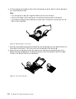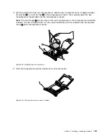
6. Remove the rear fan assembly. See “Rear fan assembly” on page 137.
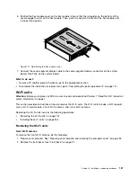
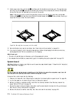
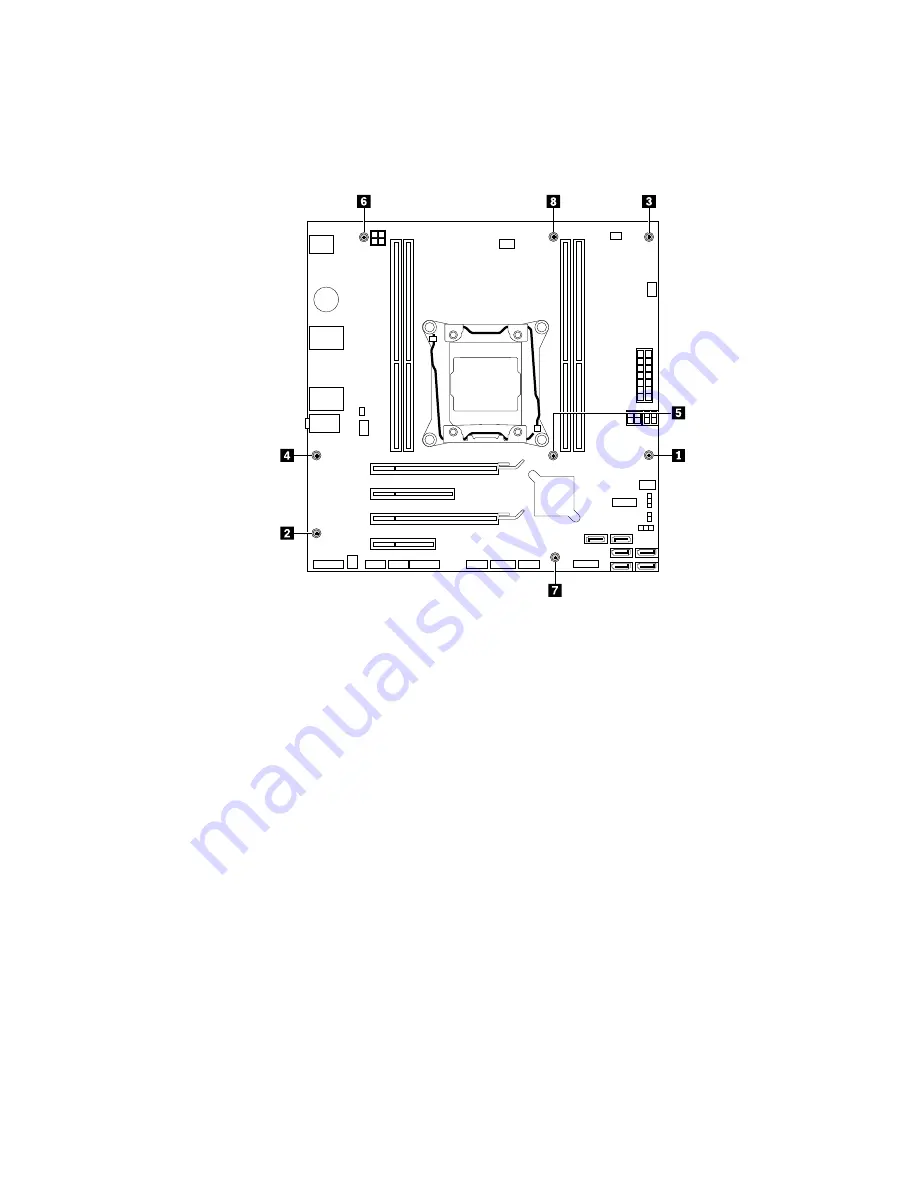
7. Remove the eight screws that secure the system board by following the sequence shown in the
following illustration.
Figure 135. Removing the eight screws that secure the system board
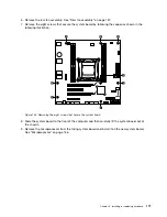
8. Slide the system board to the front of the computer and then carefully lift the system board out of
the chassis.
9. Remove the microprocessor from the failing system board and install it on the new system board.
See “Microprocessor” on page 166.
.
Installing or replacing hardware
171
Summary of Contents for ThinkStation P410
Page 1: ...ThinkStation P410 Hardware Maintenance Manual Machine Types 30B2 and 30B3 ...
Page 6: ...iv ThinkStation P410 Hardware Maintenance Manual ...
Page 8: ...vi ThinkStation P410 Hardware Maintenance Manual ...
Page 16: ...8 ThinkStation P410 Hardware Maintenance Manual ...
Page 20: ...12 ThinkStation P410 Hardware Maintenance Manual ...
Page 21: ...1 2 Chapter 1 Read this first Important safety information 13 ...
Page 22: ...1 2 14 ThinkStation P410 Hardware Maintenance Manual ...
Page 27: ...1 2 Chapter 1 Read this first Important safety information 19 ...
Page 28: ...1 2 20 ThinkStation P410 Hardware Maintenance Manual ...
Page 31: ...Chapter 1 Read this first Important safety information 23 ...
Page 52: ...44 ThinkStation P410 Hardware Maintenance Manual ...
Page 64: ...56 ThinkStation P410 Hardware Maintenance Manual ...
Page 102: ...94 ThinkStation P410 Hardware Maintenance Manual ...
Page 184: ...176 ThinkStation P410 Hardware Maintenance Manual ...
Page 188: ...180 ThinkStation P410 Hardware Maintenance Manual ...
Page 190: ...182 ThinkStation P410 Hardware Maintenance Manual ...
Page 192: ...184 ThinkStation P410 Hardware Maintenance Manual ...
Page 200: ...192 ThinkStation P410 Hardware Maintenance Manual ...
Page 204: ...196 ThinkStation P410 Hardware Maintenance Manual ...
Page 207: ......
Page 208: ......

