


Locating parts on the system board
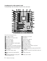
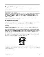
The following figure shows the locations of the parts on the system board.
Figure 4. System board part locations
1
PS/2 adapter connector
2
Microprocessor fan connector
3
Microprocessor 12 V power connector
4
Microprocessor
5
Memory fan connector
6
Hard disk drive fan connector
7
Memory slot 3 (DIMM3)
8
Memory slot 7 (DIMM7)
9
Memory slot 4 (DIMM4)
10
Memory slot 8 (DIMM8)
11
Hard disk drive enablement module (optional)
12
24-pin power connector
13
Front fan connector
14
Internal USB 2.0 connector
15
SATA connectors 1 and 2 (SATA 3.0 connectors)
16
SATA connectors 3 and 4 (SATA 2.0 connectors)
17
SATA/SAS connectors for the hard disk drive (3)
18
Hard disk drive LED (LSI)
19
Cover presence switch connector (Intrusion
switch connector)
20
Front USB 2.0 connector (for connecting the front USB 2.0
ports if applicable)
21
Clear CMOS /Recovery jumper
22
Internal USB 2.0 connector (for connecting the media card
reader)
23
eSATA connector (for connecting eSATA
adapter)
24
Auxiliary LED connector
25
Front panel connector (for connecting LED
indicators and power switch)
26
Thermal sensor connector
12
ThinkStation S30 User Guide
Summary of Contents for ThinkStation S30
Page 1: ...ThinkStation S30 User Guide ...
Page 6: ...iv ThinkStation S30 User Guide ...
Page 12: ...x ThinkStation S30 User Guide ...
Page 28: ...16 ThinkStation S30 User Guide ...
Page 44: ...32 ThinkStation S30 User Guide ...
Page 50: ...38 ThinkStation S30 User Guide ...
Page 78: ...66 ThinkStation S30 User Guide ...
Page 92: ...80 ThinkStation S30 User Guide ...
Page 102: ...90 ThinkStation S30 User Guide ...
Page 128: ...116 ThinkStation S30 User Guide ...
Page 136: ...124 ThinkStation S30 User Guide ...
Page 140: ...128 ThinkStation S30 User Guide ...
Page 144: ...132 ThinkStation S30 User Guide ...
Page 148: ...136 ThinkStation S30 User Guide ...
Page 149: ......
Page 150: ......


