30
System overview
Power cooling module
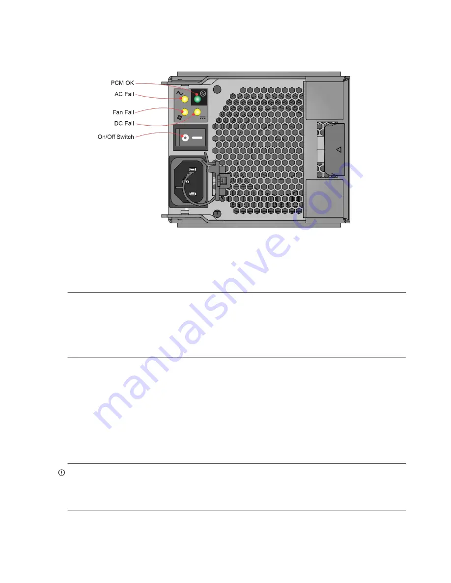
shows the power cooling module (PCM) used in controller enclosures and optional expansion
enclosures. The example shows a PCM oriented for use in the left PCM slot of the enclosure rear panel.
Figure 22 Power cooling module (PCM) detail
2U enclosure chassis
The 2U chassis consists of a sheet metal enclosure with an integrated midplane PCB and module runner system.
NOTE:
Supported 2U chassis form factors used for configuring RBODs and EBODs:
•
2U12 chassis configured with 12 LFF disks: see
•
2U24 chassis configured with 24 SFF disks: see
•
2U12 empty chassis with midplane: see
•
2U24 empty chassis with midplane: see
•
The chassis has a 19-inch rack mounting that enables it to be installed onto standard 19-inch racks and uses two
EIA units of rack space (3.5") for a 2U enclosure.
•
The midplane PCB can support either 12 or 24 disk drive connections.
•
There are either 12 or 24 drive slots at the front of the enclosure, in horizontal (12) or vertical (24) orientation,
as defined by the enclosure variant. See also
. Each drive slot holds a plug-in
drive carrier module that can hold these drive types, dependent upon the enclosure type:
2U12 enclosure: 12 low profile (1" high) 3.5" LFF disk drives, held horizontally.
2U24 enclosure: 24 low profile (5/8” high) 2.5" LFF disk drives, held vertically.
•
At the rear, the chassis assembly can hold a maximum of two PCMs and two SBB-compliant IOMs.
IMPORTANT:
The DS Series and DS EXP/D3284 storage enclosures support SBB dual-controller configuration only.
If a partner controller fails, the storage system will fail over and run on a single controller module until the
redundancy is restored. An IOM must be installed in each IOM slot to ensure sufficient air flow through the enclosure
during operation.


