130 Module removal and replacement
The Display LED on the Ops panel located on the enclosure left ear will be blinking green when the above
command is invoked.
NOTE:
See the CLI Reference Guide for additional information.
Removing an IOM
IMPORTANT:
Considerations for removing controller modules:
•
In a dual-controller environment, you may hot-swap a single controller module in an operational enclosure,
provided you first shut down the faulty controller using the SMC or the CLI.
•
In a dual-controller environment—if replacing both controller modules—you must adhere to the instructions
provided in
.
•
Do not remove a faulty module unless its replacement is on-hand. All modules must be in place when the
system is in operation.
NOTE:
See CAUTION bullets regarding
electrostatic discharge
and
anti-static protection
on
Illustrations in the controller module replacement procedures show rear panel views of the enclosure, and IOMs are
properly aligned for insertion into the rear panel of the enclosure.
1.
Verify that you have successfully shut down the controller module using the SMC or the CLI.
2.
Locate the enclosure whose UID LED (Ops panel on enclosure front left ear) is illuminated, and within the
enclosure, locate the controller module whose OK to Remove LED is blue (rear panel).
3.
Disconnect any cables connected to the controller.
Label each cable to facilitate re-connection to the replacement IOM.
4.
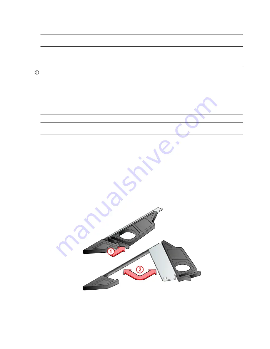
Grasp the module latch between the thumb and forefinger, and squeeze the flange and handle together to release
the latch handle from its docking member as shown in the first illustration within
.
5.
Swing the latch handle open as shown in the second illustration within the figure.
Figure 90 IOM latch operation


