background image


2


Content


Disclaimer


...............................................................................................................................................................


6


Trademarks


and


Copyrights


...................................................................................................................................


7


Safety


Information


.................................................................................................................................................


8


Chapter


1


Introduction


.........................................................................................................................................


12


1.


1


PRODUCT


OVERVIEW


................................................................................................................................


12


1.


2


FEATURES


..................................................................................................................................................


12


1.2.1


HIGH


RELIABILITY


................................................................................................................................


12


1.2.2


HIGHLY


AVAILABILITY


..........................................................................................................................


12


1.2.3


HIGH


EXPANDABILITY


..........................................................................................................................


12


1.2.4


HIGH


MANAGEABILITY


........................................................................................................................


12


1.


3


FEATURES


AND


SPE


CIFICATIONS


..............................................................................................................


13


Chapter


2


Structural


Characteristics


....................................................................................................................


15


2.


1


STRUCTURAL


CHARACTERI


STICS


..............................................................................................................


15


2.1.1


FRONT


VIEW


OF


THE


SERVER


..............................................................................................................


15


2.1.2


REAR


VIEW


OF


THE


SERVER


.................................................................................................................


16


2.1.3


FRONT


CONTROL


PANEL


....................................................................................................................


16


2.1.4


MB


ASSEMBLY


MAIN


COMPONENTS


..................................................................................................


18


2.


2


INSTALLING,


REMOVING


AND


REPLACING


HARDWARE


...........................................................................


18


2.2.1


Exploded


Drawing


...............................................................................................................................


19


2.2.2


REMOVING


AND


REINSTALLING


THE


RACK


HANDLE


...........................................................................


20


2.2.3


REMOVING


AND


REINSTALLING


THE


SERVER


COVER


.........................................................................


20


2.2.4


REMOVING


AND


REINSTALLING


THE


FRONT


I/O


MODULE


.................................................................


21


2.2.5


REMOVING


AND


REINSTALLING


THE


BACK


PLANE


.............................................................................


21


2.2.6


REMOVING


AND


REINSTALLING


THE


SUPERCAP


AND


HOLDER


..........................................................


22


2.2.7


REMOVING


AND


REINSTALLING


THE


COOLING


SHROUD


...................................................................


23


2.2.8


REMOVING


OR


INSTALLING


A


MEMORY


MODULE


.............................................................................


23


2.2.9


REPLACING


THE


RISER


1,


2


..................................................................................................................


24


2.2.10


REMOVING


OR


INSTALLING


A


PCIE


CARD


AND


PCI


CAGE


.................................................................


24


2.2.11


INSTALLING


OR


REMOVING


THE


REAR


HDD


MODULE


......................................................................


25


2.2.12


INSTALLING


OR


REPLACING


A


CPU,


HEAT


SINK


AND


CPU


DUMMY


..................................................


27


Summary of Contents for ThinkSystem HR630X

Page 1: ...ThinkSystem User Guide HR630X User Manual V1 0 Please read this manual before using the product ...

Page 2: ...Y MAIN COMPONENTS 18 2 2 INSTALLING REMOVING AND REPLACING HARDWARE 18 2 2 1 Exploded Drawing 19 2 2 2 REMOVING AND REINSTALLING THE RACK HANDLE 20 2 2 3 REMOVING AND REINSTALLING THE SERVER COVER 20 2 2 4 REMOVING AND REINSTALLING THE FRONT I O MODULE 21 2 2 5 REMOVING AND REINSTALLING THE BACK PLANE 21 2 2 6 REMOVING AND REINSTALLING THE SUPERCAP AND HOLDER 22 2 2 7 REMOVING AND REINSTALLING THE...

Page 3: ...BIOS Setup 34 3 1 BIOS Setup Description 34 3 2 BIOS Setup Main Menu 34 3 3 Main Menu 34 Chapter 4 BMC Setup 75 4 1 Overview of the Lenovo ThinkSystem Management Module 75 4 2 Configuration of the ThinkSystem Remote Management Module 76 Prestart 77 Log on 79 Navigation 80 Log out 82 4 4 ThinkSystem Remote Management Module Web console options 83 4 4 1 Dashboard 83 4 4 2 Dashboard Information 83 4 ...

Page 4: ...9 8 PAM Order Settings 94 4 9 9 Platform Event Filter 95 4 9 10 RAID Management 95 4 9 11 Services 96 4 9 12 SMTP Settings 96 4 9 13 SSL Settings 97 4 9 14 System Firewall 98 4 9 15 User Management 98 4 9 16 Video Recording 99 4 9 17 Web Server Instances 99 4 10 Remote Control 100 4 11 Image Redirection 100 4 12 Power Control 101 4 13 Maintenance 101 4 13 1 Backup Configuration 102 4 13 2 Firmware...

Page 5: ... SYSTEM OPERATION PROBLEMS 106 5 4 RESOLVING OTHER P ROBLEMS 107 5 4 1 MONITOR DISPLAY PROBLEMS 107 5 4 2 WAVY LINES ON THE SCREEN 107 5 4 3 CLEARING SYSTEM CONFIGURATION 107 5 4 4 REPLACING THE SYSTEM BOARD BATTERY 107 5 4 5 COMMON PROBLEMS ENCOUNTERED WHILE OPERATING AND USING THE SYSTEM 108 Appendix Terms and Abbreviations 109 ...

Page 6: ...part of the services provided by Lenovo Lenovo shall not be responsible for the accuracy and reliability of these websites and of the information contained therein Such websites should only be accessed at the user s own risks The contents of this manual shall not be construed to constitute any expressed or implied warranty or guarantee by Lenovo for its products or services including but not limit...

Page 7: ...are trademarks or registered trademarks of the Microsoft Corporation The names of other companies products or services may be trademarks or service marks of other companies The software accompanying this Product are provided based on the terms and conditions of the end user license agreement and may only be used and copied as stipulated in the end user agreement Copyright Lenovo Beijing Co Ltd 201...

Page 8: ...r cords telecommunications systems networks and modems before you open the device covers unless otherwise instructed in the installation and configuration procedures Connect and disconnect cables as described in the following table when installing moving or opening covers on this Product or the attached devices The power button on the front panel does not disconnect the internal system from the AC...

Page 9: ...2 kg 70 55 kg 121 32 kg 70 5 lb 55 kg 121 2 lb 100 kg 220 5 lb CAUTION Use safe practices when lifting Statement 5 CAUTION The power control button on the device and the power switch on the power supply do not turn off the electrical current supplied to the device The device may have more than one power cord To remove all electrical current from the device ensure that all power cords are disconnec...

Page 10: ...is a potential fire hazard and shock hazard under certain conditions To avoid these hazards ensure that your system electrical requirements do not exceed branch current ratings at the installation site Statement 13 CAUTION Ensure that the rack is secured properly to avoid tipping when the server unit is extended on the rails Statement 14 CAUTION Some accessory or option board outputs exceed Class ...

Page 11: ...ters in length Torque the wiring terminal screws to 1 4 newton meters 12 inch pounds Provide a readily available approved and rated disconnect device in the field wiring Statement 17 CAUTION This Product contains a Class 1M laser Do not view directly with optical instruments Statement 18 CAUTION Do not place any object on top of rack mounted products Statement 19 CAUTION Hazardous moving parts Kee...

Page 12: ...e reliable and high speed storage subsystems 4 Uses highly reliable server dedicated power supply to ensure uninterrupted and stable operation 1 2 2 HIGHLY AVAILABILITY 1 Supports two Intel Xeon Skylake Server 2S processors The new processor supports up to 28 cores up to 10 4 GT s UPI hence significantly improving data processing capabilities and meeting performance standards for servers in multi ...

Page 13: ... 2 rear 1 internal USB2 0 x 2 front RJ45 x 1 NIC Management System fan Support hot plug Equipped with automatic energy saving and noise reduction technologies Compatible with Windows Server 2008 SP2 x86 Windows Server 2008 R2 with SP1 including Hyper V Windows 8 1 Windows Server 2012 including Hyper V Windows Server 2012 R2 SUSE LINUX Enterprise Server 11 SP3 SUSE LINUX Enterprise Server 12 SUSE L...

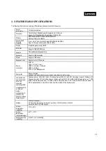
Page 14: ...ng without original shipping packaging Power supply 200 240V 50Hz 60Hz voltage 100 127V 50Hz 60Hz Power 750W 1 1 hot swap redundant power supply 550W 1 1 hot swap redundant power supply Dimensions 43mm 481 7m 748 6mm height width depth with rack handles 43mm 434 4mm 734mm height width depth without rack handles ...

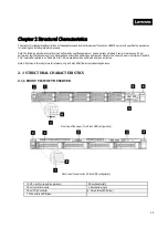
Page 15: ...d all warnings and cautions stated in the Lenovo Server User Guide Read Me First hereinafter referred to as Read Me First All removals should be performed strictly as instructed Note All pictures in this chapter are for reference only and may differ from actual product appearance 2 1 STRUCTURAL CHARACTERI STICS 2 1 1 FRONT VIEW OF THE SERVER Front view of the server 10 2 5 inch HDD configuration F...

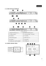
Page 16: ...ull high half length PCIe card slot 3 Hot swap power supply 1 4 Hot swap power supply 2 option parts 5 Serial connector 6 VGA connector 7 System ID button with LED 8 USB3 0 connector x2 9 2 5 inch HDD 1 10 2 5 inch HDD 2 11 Network connector system management 12 OCP Mezz Card 2 1 3 FRONT CONTROL PANEL ...

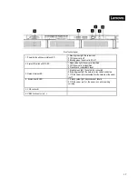
Page 17: ... 2 Off the server is not identified 3 Press 5 secs initiate BMC reset 1 Steady green light the network is connected 3 Network status LED 2 Blinking green light the network is connected and active 3 Off the server is disconnected from the network or the server is off 4 System health LED 1 Steady yellow light key component failure 2 Off the server is off or the server is on and is working correctly ...

Page 18: ...ing operations should be performed on ESD workbenches Where ESD workbenches are not available minimize ESD damage by doing the following 1 Wear an ESD wrist strap and connect it to a metal part of the server 2 Touch the metal casing of the server chassis before handling other server components 3 Ensure that part of your body is in contact with the metal chassis when removing or installing a compon...

Page 19: ...Supercap holder 10 Front module 10x2 5 inch 11 Front module 4x3 5 inch 12 Rear HDD module 13 PSU 14 PSU cover 15 NIC card 16 Chassis 17 3 5 inch HDD 18 2 5 inch HDD 19 3 5 inch HDD Dummy 20 2 5 inch HDD Dummy 21 Fan module 22 Back plane _8x2 5 inch 23 Back plane _10x2 5 inch 24 Back plane _4x3 5 inch 25 DIMM 26 CPU 27 CPU Heat sink 28 MB Assembly ...

Page 20: ...k handle To reinstall reverse the steps above 2 2 3 REMOVING AND REINSTALLING THE SERVER COVER Do not proceed before reading and understanding the Safety Precautions section of this chapter and Read Me First To remove the server cover do the following 1 Turn off all attached devices and the server 2 Disconnect the AC power cord from the electrical outlet 3 Unlock the latch with screwdriver Step 1 ...

Page 21: ...se the steps above 2 2 5 REMOVING AND REINSTALLING THE BACK PLANE Do not proceed before reading and understanding the Safety Precautions section of this chapter and Read Me First To remove the back plane do the following 1 Turn off all attached devices and the server 2 Disconnect the AC power cord from the electrical outlet 3 Remove the server cover See Removing and reinstalling the server cover 4...

Page 22: ...p Step 2 4 3 5 inch HDD configuration To reinstall reverse the steps above 4 For 10x2 5 inch HDD configuration Location B the holder dummy needs to be disassembled before supercap being installed i Push down the buckle on the dummy holder Step 1 ii Slide and lift up the dummy holder Step 2 iii Align the supercap holder to the locating holes put the holder and slide in to fix it Step 3 10 2 5 inch ...

Page 23: ...understanding the Safety Precautions section of this chapter and Read Me First To install a memory module do the following 1 Turn off all attached devices and the server 2 Disconnect the AC power cord from the electrical outlet 3 Remove the server cover See Removing and reinstalling the server cover 4 Remove the cooling shroud See Removing and reinstalling the cooling shroud 5 Open the retaining c...

Page 24: ...t it straight up and off the chassis Removing the riser 1 module Removing the riser 2 module To reinstall reverse the steps above 2 2 10 REMOVING OR INSTALLING A PCIE CARD AND PCI CAGE Do not proceed before reading and understanding the Safety Precautions section of this chapter and Read Me First To remove a PCIe card on riser module do the following 1 Turn off all attached devices and the server ...

Page 25: ...eight 8 Support 1xCPU config Half length 2 Half height 16 Support 1xCPU config Full height half length 3 Half height 16 Support 2xCPU config half length 2 2 11 INSTALLING OR REMOVING THE REAR HDD MODULE Do not proceed before reading and understanding the Safety Precautions section of this chapter and Read Me First To remove rear HDD module assembly do the following 1 Turn off all attached devices ...

Page 26: ... the AC power co he server cover S nect the cables on rear HDD module he rear HDD mod ables connected t everse the steps ord from the elec See Removing a n MB assembly s e ule cover to the rear HDD m above ctrical outlet and reinstalling th ide position A B module position he server cover B 1 2 26 ...

Page 27: ...to Push CPU into clip 6 Align with triangle mark to push CPU Clip assembly onto the heat sink base 7 Install the heat sink with CPU onto the socket 8 Screw the heat sink with torque screwdriver and following the sequence in figure Note Do not touch the pins on the CPU socket to avoid damaging them To install the CPU dummy Align to DIMM slots and push down the CPU dummy To remove reverse the steps ...

Page 28: ...to above G OR REPL g and understand r a 2 5 3 5 inch ho my tray y tray out of the ch above and reinstalling th acket screw Step o the system boar LACING THE ding the Safety P ot swap drive do hassis Grab the ha Removing the d he server cover p1 and remove th rd then lift the OC Removing an O E DUMMY Precautions secti o the following andle of the 2 5 3 dummy tray of a 2 he bracket Step2 CP card off...

Page 29: ... G OR REPL g and understand upply into the cha LACING A H ding the Safety P e following wap drive See F ushing the release out of the chassis Remo he available bays Order of insta LACING A H ding the Safety P assis until it snap HOT SWAP Precautions secti Figure below to o e latch of a 2 5 3 s oving a 2 5 3 5 inc in the order num llation for 2 5 3 5 HOT SWAP Precautions secti s into position DRIVE...

Page 30: ...M 2 storages S he latch to lock M emble the M 2 sto the latch Step1 the M 2 storage f ut the M 2 module swap power supp G OR REPL g and understand he following See Removing a out of the server above G THE M 2 g and understand s and the server ord from the elec ge module e connector Step Step 2 M 2 module Step orage module and pull out the l from the lock Ste e from the connec ply out LACING A SY d...

Page 31: ...stalling the server cover 5 Insert the M 2 storage module through the guide pins between the PSU cage and left Riser2 6 Plugs the SATA cable and power cable to SATA port 0 1 and power connector reference 3 1 Section To reinstall reverse the steps above ...

Page 32: ...ee INSTALLING OR REPLACING A HOT SWAP POWER SUPPLY 4 Remove the server cover See Removing and reinstalling the server cover 5 Remove the Riser assembly See Replacing the Riser 1 2 6 Remove the system fan See INSTALLING OR REPLACING A SYSTEM FAN 7 Grab the plungers 8 Slide to front side and lift up the MB assembly To install 1 Handle the MB assembly through grabbing the plungers Position 1 2 2 Alig...

Page 33: ...ed length of 730 mm which may be used with cable management clips at full length The Rail Kit Installation Guide may be found in the rail kit package Refer to the Rail Kit Installation Guide for rail kit installation instructions Warning Installation of the rail kit should be performed by two or more people Some risk is involved when moving and installing the server Be sure to follow the instructi...

Page 34: ...up Main Menu Item Description Main Basic BIOS parameter setting Advanced Advance BIOS parameter setting Server Mgmt Server management parameter setting Security Security parameter setting Boot Boot option parameter setting Save Exit Save parameter and exit 3 3 Main Menu Item Option Description BIOS Information BIOS Vendor Read Only Display BIOS Vendor Core Version Read Only Display Core Version Co...

Page 35: ...ths 1 12 Days dependent on month System Time HH MM SS Set the Time Use Tab to switch between Time elements Processor Information Table Sub of Main Menu Item Option Description Processor BSP Revision Read Only Display Processor BSP Revision Processor Socket Read Only Display Processor Socket0 Socket1 Processor ID Read Only Display current Processor ID Processor Frequency Read Only Display current P...

Page 36: ...n Read Only Not Present Memory Information Sub of Main Menu Socket0 ChA Dimm0 DIMM is Present DIMM Status Enabled DIMM Details 2400MT s Samsung DRx4 16GB RDIMM Socket1 ChA Dimm0 DIMM is Present DIMM Status Enabled DIMM Details 2400MT s Samsung DRx4 16GB RDIMM Empty Empty Advanced Menu Item Option Description iSCSI Configuration In iSCSI Configuration Table Configure the iSCSI parameters Intel Virt...

Page 37: ...guration In Processor Configuration Table Processor Configuration Chipset Configuration In Chipset Configuration Chipset Configuration SATA Configuration In SATA Configuration SATA Configuration Memory Configuration In Memory Configuration Memory Configuration PCIE per port control In PCIE per port control PCIE per port control iSCSI Configuration Table Sub of Advanced Menu Item Description iSCSI ...

Page 38: ...iption Configuration Security Device Support Disable Enable Enables or Disables BIOS support for security device O S will not show Security Device TCG EFI protocol and INT1A interface will not be available NO Security Device Found Serial Port Console Redirection Table Sub of Advanced Menu Item Description AST2500 Super IO Configuration One Blank Line COM0 Configuration Serial Port Disabled Enabled...

Page 39: ... 6 7 9 10 11 12 IO 2E8h IRQ 3 4 5 6 7 9 10 11 12 Select an optimal settings for Super IO Device One Blank Line COM0 Console Redirection Disabled Enabled Console Redirection Enable or Disable Console Redirection Settings The settings specify how the host computer and the remote computer which the user is using will exchange data Both computers should have the same or compatible settings COM0 SOL Co...

Page 40: ...low Control None Hardware RTS CTS Flow control can prevent data loss from buffer overflow When sending data if the receiving buffers are full a stop signal can be sent to stop the data flow Once the buffers are empty a start signal can be sent to re start the flow Hardware flow control uses two wires to send start stop signals VT UTF8 Combo Key Support Disabled Enabled Enable VT UTF8 Combination K...

Page 41: ...d Mark Space A parity bit can be sent with the data bits to detect some transmission errors Even parity bit is 0 if the num of 1 s in the data bits is even Odd parity bit is 0 if num of 1 s in the data bits is odd Mark parity bit is always 1 Space Parity bit is always 0 Mark and Space Parity do not allow for error detection They can be used as an additional data bit Stop Bits 1 2 Stop bits indicat...

Page 42: ...Console Redirection Legacy Console Redirection Settings Legacy Console Redirection Settings Legacy Serial Redirection Port COM0 CO M1 Select a COM port to display redirection of Legacy OS and Legacy OPROM Messages One Blank line Serial Port for Out of Band Management Windows Emergency Management Services EMS Console Redirection Disabled Enabled Console Redirection Enable or Disable Console Redirec...

Page 43: ...e Sub of Advanced Menu PCI SubsystemSettings PCI PCI X and PCI Express Settings PCI Bus Driver Version A5 01 11 One Blank line PCI Devices Common Settings Above 4G Decoding Disabled Enabled Enables or Disables 64bit capable Devices to be Decoded in Above 4G Address Space Only if System Supports 64 bit PCI Decoding SR IOV Support Disabled Enabled If system has SR IOV capable PCIe Devices this optio...

Page 44: ...tion settings etc Compatibility Support Module Configuration One blank line CSM Support Disabled Enabled Enable Disable CSM Support One blank line CSM16 Module Version 7 8 One blank line GateA20 Active Upon Request Always UPON REQUEST GA20 can be disabled using BIOS services ALWAYS do not allow disabling GA20 this option is useful when any RT code is executed above 1MB Option ROM Messages Force BI...

Page 45: ...devices other than Network Storage or Video NVMe Configuration Table Sub of Advanced Menu NVMe Configuration NVMe Device Options Settings NVMe controller and Drive information No NVME Device Found USB Configuration Table Sub of Advanced Menu USB Configuration USB Configuration Parameters USB Configuration One blank line USB Module Version 17 One blank line USB Controllers 1 XHCI USB Devices 1 Driv...

Page 46: ...able Ena ble Enable Disable this USB Physical Connector physical port Once disabled any USB devices plug into the connector will not be detected by BIOS or OS USB HS Physical Connector 2 Disable Disable Ena ble Enable Disable this USB Physical Connector physical port Once disabled any USB devices plug into the connector will not be detected by BIOS or OS USB HS Physical Connector 3 Disable Disable...

Page 47: ...ut 10 sec 20 sec 30 sec 40 sec USB mass storage device Start Unit command time out Device power up delay Auto Manual Maximum time the device will take before it properly reports itself to the Host Controller Auto uses default value for a Root port it is 100 ms for a Hub port the delay is taken One blank line Mass Storage Devices AMI Virtual CDROM0 1 00 Auto Floppy Forced FDD Hard Disk CD ROM Mass ...

Page 48: ...P states Lower Limit Default Max Non Turbo P states Lower Limit Hardware P States Disable Native Mode Out of Band Mode Native Mode with No Legacy Support Disable Hardware chooses a P state based on OS Request Legacy P States Native Mode Hardware chooses a P state based on OS guidance Out of Band Enhanced Halt State C1E Disable Enable Enables the Enhanced C1E state of the CPU takes effect after reb...

Page 49: ...ding Software Method to Enable Disable Logical Processor threads Socket0 Core Disable Bitmap Hex 0 0 Enable all cores FFFFFFF Disable all cores Socket1 Core Disable Bitmap Hex 0 0 Enable all cores FFFFFFF Disable all cores Hardware Prefetcher Enable Disable MLC Streamer Prefetcher MSR 1A4h Bit 0 Adjacent Cache Prefetch Enable Disable MLC Spatial Prefetcher MSR 1A4h Bit 1 DCU Streamer Prefetcher En...

Page 50: ...A Disable Enable Select Dma Enable Disable for each CB device No Snoop Disable Enable No Snoop Enable Disable for each CB device IOAT Function 2 Items DMA Disable Enable Select Dma Enable Disable for each CB device No Snoop Disable Enable No Snoop Enable Disable for each CB device IOAT Function 3 Items DMA Disable Enable Select Dma Enable Disable for each CB device No Snoop Disable Enable No Snoop...

Page 51: ... Enable Disable for each CB device IOAT Function 7 Items DMA Disable Enable Select Dma Enable Disable for each CB device No Snoop Disable Enable No Snoop Enable Disable for each CB device Sck1 IOAT Config DCA Disable Enable DCA Enable Disable for this specific socket IOAT Function 0 Items DMA Disable Enable Select Dma Enable Disable for each CB device No Snoop Disable Enable No Snoop Enable Disabl...

Page 52: ...le Disable for each CB device IOAT Function 4 Items DMA Disable Enable Select Dma Enable Disable for each CB device No Snoop Disable Enable No Snoop Enable Disable for each CB device IOAT Function 5 Items DMA Disable Enable Select Dma Enable Disable for each CB device No Snoop Disable Enable No Snoop Enable Disable for each CB device IOAT Function 6 Items DMA Disable Enable Select Dma Enable Disab...

Page 53: ...able Non Isoch VT_D Engine Pass Through DMA support ATS Enable Disable Enable Disable Non Isoch VT_D Engine ATS support Posted Interrupt Enable Disable Enable Disable VT_D posted interrupt Coherency Support Non Isoch Enable Disable Enable Disable Non Isoch VT_D Engine Coherency support Execute Disable Bit Disable Enable When disabled forces the XD feature flag to always return 0 Chipset Configurat...

Page 54: ...gable sSATA Port 2 Not Installed Hot Plug Disable Enable Designates this port as Hot Pluggable sSATA Port 3 Not Installed Hot Plug Disable Enable Designates this port as Hot Pluggable sSATA Port 4 Not Installed Hot Plug Disable Enable Designates this port as Hot Pluggable sSATA Port 5 Not Installed Hot Plug Disable Enable Designates this port as Hot Pluggable SATA Port 0 Not Installed Hot Plug Dis...

Page 55: ...mory RAS Settings Memory RAS Configuration Setup One blank line Static Virtual Lockstep Mode Disable Ena ble Enable Static Virtual Lockstep mode Mirror mode Disable Mirror Mode 1LM Mirror Mode 2LM Mirror Mode will set entire 1LM 2LM memory in system to be mirrored consequently reducing the memory capacity by half Mirror Enable will disable XPT Prefetch Enable Partial Mirror Disable Partial Mirror ...

Page 56: ...00 1066 1200 1333 1400 1600 1800 1866 2000 2133 2200 2400 2600 2666 2800 OvrClk 2933 OvrClk 3000 OvrClk 3200 OvrClk 3400 OvrClk 3466 OvrClk 3600 OvrClk 3733 OvrClk 3800 OvrClk 4000 OvrClk 4200 OvrClk 4266 OvrClk 4400 OvrClk Maximum Memory Frequency Selections in Mhz Do not select Reserved Numa Disable Enable Enable or Disable Non uniform Memory Access NUMA SNC Disable Enable Auto Sub NUMA Clusteri...

Page 57: ...1C PCI E Port Auto Disable Enable In auto mode the BIOS twill remove the EXP port if there is no device or errors on that device and the device is not HP capable Disable is used to disable the Link Speed Auto Gen 1 2 5 GT s Gen 2 5 GT s Gen 3 8 GT s Choose Link Speed for this PCIe port Socket 0 PcieBr2D00F0 Port 2A PCI E Port Auto Disable Enable In auto mode the BIOS twill remove the EXP port if t...

Page 58: ...that device and the device is not HP capable Disable is used to disable the Link Speed Auto Gen 1 2 5 GT s Gen 2 5 GT s Gen 3 8 GT s Choose Link Speed for this PCIe port Socket 0 PcieBr5D00F0 MCP 1 PCI E Port Auto Disable Enable In auto mode the BIOS twill remove the EXP port if there is no device or errors on that device and the device is not HP capable Disable is used to disable the Link Speed A...

Page 59: ...s Choose Link Speed for this PCIe port Socket 1 PcieBr1D02F0 Port 1C PCI E Port Auto Disable Enable In auto mode the BIOS twill remove the EXP port if there is no device or errors on that device and the device is not HP capable Disable is used to disable the Link Speed Auto Gen 1 2 5 GT s Gen 2 5 GT s Gen 3 8 GT s Choose Link Speed for this PCIe port Socket 1 PcieBr1D03F0 Port 1D PCI E Port Auto D...

Page 60: ...there is no device or errors on that device and the device is not HP capable Disable is used to disable the Link Speed Auto Gen 1 2 5 GT s Gen 2 5 GT s Gen 3 8 GT s Choose Link Speed for this PCIe port Socket 1 PcieBr3D02F0 Port 3C PCI E Port Auto Disable Enable In auto mode the BIOS twill remove the EXP port if there is no device or errors on that device and the device is not HP capable Disable i...

Page 61: ...Disable is used to disable the Link Speed Auto Gen 1 2 5 GT s Gen 2 5 GT s Gen 3 8 GT s Choose Link Speed for this PCIe port Server Management Menu Item Option Description Server Management BMC Self Test Status Read Only Ok Display PASSED BMC Device ID Read Only Display BMC Device ID BMC Device Revision Read Only Display BMC Device Revision IPMI Version Read Only Display IPMI Version One Blank Lin...

Page 62: ...ystem should respond if the OS Boot Watchdog Timer expires Not available if OS Boot Watchdog Timer is disabled Serial Mux Enabled Disabled Press Enter to enable or disable Serial Mux configuration One Blank Line BMC DNS Configuration In BMC DNS Configuration Table Press Enter to Configure BMC DNS System Event Log In System Event Log Table Press Enter to change the SEL event log configuration BMC s...

Page 63: ... name is Serial name One blank line Register BMC shared Disabled Enabled If bonding mode show Bonding Enabled Disabled Register Method Nsupdate DHCP Client FQDN Hostname If bonding mode show Register method Nsupdate DHCP Client FQDN Hostname dedicated Disabled Enabled If bonding mode hide the item Register Method Nsupdate DHCP Client FQDN Hostname If bonding mode hide the item One blank line Domai...

Page 64: ...ions to a full SEL One blank line Custom EFI Logging Options Log EFI Status Codes Disabled Both Error code Progress code Disable the logging of EFI Status Codes or log only error code or only progress code or both One blank line NOTE All values changed here do not take effect until computer is restarted Bmc self test log Table Sub of Server Management Menu Bmc self test log logs the report returne...

Page 65: ... to BMC FRU spec Chassis Serial Number Read Only Please refer to BMC FRU spec System UUID Read Only Please refer to BMC FRU spec BMC network configuration Table Sub of Server Management Menu BMC network configuration Configure IPV4 support One blank line NCSI Switch Don t Change OCP MEZZ Card Type A Riser1 Pcie Lan NCSI Cable LAN share NCSI connects to on board LAN SFP share NCSI connects to on bo...

Page 66: ... modify any BMC network parameters during BIOS phase Current Configuration Address source DHCP Station IP address Enter station IP address Subnet mask Enter subnet mask Station MAC address Router IP address Enter router IP address Router MAC address Enter router MAC address VLAN_ID VLAN ID 12 bit Range 0 4095 0 if VLAN ID not used VLAN ID 0 1 4095 are reserved VLAN ID s One blank line Configure IP...

Page 67: ...configure LAN channel parameters statically or dynamically by BIOS or BMC Unspecified option will not modify any BMC network parameters during BIOS Current Configuration Address source DHCP Station IPV6 address Prefix length IPV6 Router IP address IPV6 address status IPV6 DHCP Algorithm View System Event Log Table Sub of Server Management Menu View remaining System Event Log Press Enter to view th...

Page 68: ...umber User Privilege Limit Reserved Enter BMC User Privilege Limit for Selected Channel One blank line Delete User BMC Delete User Details One blank line User Name Enter BMC User Name User Password Enter BMC User Password If the password has been forgotten just enter anything and change the password later One blank line Change User Settings Press Enter to Change User Settings BMC Change User Setti...

Page 69: ...be dropped if no ACK NACK received by time retries expire SOL Retry Interval 50 Range 0 255 Retry Interval in 10 ms increments 0 Retries sent back to back Security Menu Item Option Description Password Description One Blank Line If ONLY the Administrator s password is set then this only limits access to Setup and is only asked for when entering Setup If ONLY the User s password is set then this is...

Page 70: ...de Secure Boot Variables can be configured without authentication Key Management Enables experienced users to modify Secure Boot variables For MLK BIOS only Provision Factory Default keys Disabled Enabled Install factory default Secure Boot keys when System is in Setup Mode For MLK BIOS only One blank line Enroll all Factory Default keys Yes No Force System to User Mode install Factory Default key...

Page 71: ...A2048 bin d EFI_CERT_SHA256 bin 2 Authenticated UEFI Variable Key source Default Custom Mixed modified from Setup menu For MLK BIOS only Delete key is only available when applicable Authorized Signatures 0 0 Set New Key Append Key Delete key Enroll Factory Defaults or load the keys from a file with 1 Public Key Certificate in a EFI_SIGNATURE_LIST b EFI_CERT_X509 DER encoded c EFI_CERT_RSA2048 bin ...

Page 72: ...IGNATURE_LIST b EFI_CERT_X509 DER encoded c EFI_CERT_RSA2048 bin d EFI_CERT_SHA256 bin 2 Authenticated UEFI Variable Key source Default Custom Mixed modified from Setup menu For MLK BIOS only Delete key is only available when applicable Boot Menu Item Option Description Boot Configuration Setup Prompt Timeout Number of seconds to wait for setup activation key 65535 0xFFFF means indefinite waiting ...

Page 73: ...er of the legacy devices in this group One Blank Line New Boot Option Policy Default Place First Place Last Controls the placement of newly detected UEFI boot options Save Exit Menu Item Option Description Save Options Save Changes and Exit Exit system setup after saving the changes Discard Changes and Exit Exit system setup without saving any changes One Blank Line Save Changes and Reset Reset th...

Page 74: ...Restore Load Default values for all the setup options Save as User Defaults Save the changes done so far as User Defaults Restore User Defaults Restore the User Defaults to all the setup options One Blank Line Boot Override List bootable device ...

Page 75: ...rver through the network Features of the ThinkSystem Remote Management Module The ThinkSystem Remote Management Module is easily accessible by remote KVM and controllable via LAN or Internet It will digitize and compress the collected video signal keyboard mouse signals and then send to the remote console Embedded with remote access and related control software the module also allows integrated re...

Page 76: ...the following 1 Press F1 as soon as you see the logo screen 2 From the BIOS setup menu select Server Management BMC Network Configuration Configuration Address Source 3 From the Configuration option you can choose STATIC or DHCP to set IP address source and Subnet mask etc 4 When you finish the configuration F10 to save the settings Table 1 IPMI 2 0 Configuration submenu Configuration Address Sour...

Page 77: ... is lenovo Besides lenovo other user names and passwords are also accepted The default user name and password are as follows Username lenovo Password len0vO The Remote Management Module is accessible through the standard HTML5 Web browser with HTTP and HTTPS HTTP HTTPS The embedded Web server provides full access permission You can access the Remote Management Module via encrypted HTTPS protocol o...

Page 78: ... Copyright Lenovo 2017 78 Figure 2 Configuring IE ESC step 2 Figure 3 Configuring IE ESC step 3 ...

Page 79: ...DMIN view the home pa sful initial logon th gement Module KVM window of emote Manageme d by the ThinkSys the following exam rected to the logo mote Managemen age of the Remote he system admin f the managed se ent Module do th stem Remote Ma mple on page of the Re nt Module enter t e Management M istrator can creat erver works you m he following anagement Modul emote Manageme he user name an Module...

Page 80: ...the specific system information and take the relevant tasks listed in the following table Table 2 Tabs on the ThinkSystem Remote Management Module home page Tabb Comments Dashboard Displays the overall information about the device status Sensor Displays all sensors status System Inventory This tab contains the following submenus CPU DIMM HDD PSU PCIE FRU Information Display FRU information include...

Page 81: ...n the network to host as media through BMC Power Control Control power Maintenance Maintenance BMC configuration and firmware Sign out Terminate the current Web Console session Note If the remote console KVM window is active it will close automatically when you are logging out After logout the Web console will back to logon screen There also are tabs on the top of the home page Table 3 Tabs on the...

Page 82: ...tic Timeout If the Web console detects no user activity within five minutes the current session will be automatically terminated If the user has opened the KVM remote console window then the Web session will not automatically timeout When the automatic timeout happens the system will inform the user to log on again if the user wants to access the Web console to take operations ...

Page 83: ... privile on nformatio page shows the s tion page Description Display prod Display pow To redirect t To set refres Display syst te Manag console and each detailed illustratio m Remote Manag mation about the ge or KVM privile n summary of the g duct information wer status and sw the host remotely sh frequency tem status gement M page is divided i ons and introducti gement Module s device status La e...

Page 84: ...re events ht Lenovo 2017 nventory List nsor nsor Read nsor readings will ecord to show mo Display syst ing be displayed her ore information a tem inventory re bout that particular sensor includiing thresholds an nd a graphical rep presentation of alll associated 84 ...

Page 85: ... 4 6 1 CP This page g 4 6 2 DIM This page g ht Lenovo 2017 tem Inve PU gives detailed info MM gives detailed info entory ormation for the C ormation for the D CPU present in th DIMM present in t is system this system 85 ...

Page 86: ...yrigh 4 6 3 HD This page g 4 6 4 PS This page g ht Lenovo 2017 DD gives detailed info U gives detailed info ormation for the H ormation for the P HDD present in th PSU present in th his system is system 86 ...

Page 87: ... FRU device n n in each field ormation for the P ation eable Unit FRU file informa ame for the selec PCIE present in th t FRU Info ation On selecting cted FRU device his system ormation g any particular F ID This page dis FRU Device ID its splays the Chassi s corresponding F is Board and Pro FRU information w oduct details if a will be displayed available for the 87 ...

Page 88: ...7 gs Repo MI Event L displays the list of e or sensor name orts og f events incurred filter options to v by different sens view those specifi sors on this device c events logged i e Click on a reco in the device ord to see the det tails of that entry Also use the 88 ...

Page 89: ... Copyrigh 4 8 2 Sys This page d 4 8 3 Au This page d ht Lenovo 2017 stem Log displays logs of sy udit Log displays logs of au ystem events for udit events for thi this device is device 89 ...

Page 90: ... Copyrigh 4 8 4 Vid This page d 4 9 Sett ht Lenovo 2017 deo Log displays logs of av tings vailable recorded d video files 90 ...

Page 91: ... Copyrigh 4 9 1 Da This page is 4 9 2 Ext This field is u ht Lenovo 2017 ate Time s used to set the ternal Use sed to set LDAP date and time on er Services Active Directory n the BMC s and RADIUS 91 ...

Page 92: ... page is u 4 9 4 Log This field is u ht Lenovo 2017 VM Mouse S used to set KVM g Settings sed to configure Setting mouse emulation the log policy for n from local windo the event log o ow to remote scre other settings een 92 ...

Page 93: ...6 Me This page is u ht Lenovo 2017 anage Licen sed to display the edia Redire used to configure nses e available servic ection Sett e the media into B ces and it s validit tings BMC for redirectio ty period and new on w incenses update e 93 ...

Page 94: ... 4 9 8 PA This page is u ht Lenovo 2017 etwork sett used to configure AM Order S used to configure tings e the network sett ettings e the PAM order f tings for the availa for user authentic able LAN channe cation into the BM els MC 94 ...

Page 95: ...r provid RAID Mana llows you to view nd Event Log ent Filter des a mechanism gement w the Storage Sum m for configuring t mmary RAID Con the BMC to take s ntroller informatio selected actions o on Physical Devic on event messag ce Information Lo ges that it receive ogical Device Info s or has internally ormation BBU 95 y ...

Page 96: ...t 4 9 12 S This page is u ht Lenovo 2017 ervices t all services runn MTP Settin used to configure ning on the BMC ngs e the SMTP settin click icon on the ngs right side of serv vice to view and m modify the service e configuration 96 ...

Page 97: ... Copyrigh 4 9 13 S This field is u ht Lenovo 2017 SL Settings sed to configure s SSL certificate in nto the BMC 97 ...

Page 98: ...4 9 15 U This page is u ht Lenovo 2017 ystem Fire sed to configure User Manag used to manage u ewall firewall setting gement users By clicking g user icon admin nistrator can add a new user and m modify or delete t the existing users s 98 ...

Page 99: ... Lenovo 2017 Video Reco sed to configure Web Server ows you to provid rding the video recordi r Instances de the number of ng function of the s backend web ser e KVM server and rver instances tha d SOL setting at would be launc ched to provide lo oad balancing 99 ...

Page 100: ... Copyrigh 4 10 Re This page is u 4 11 Im This page is u ht Lenovo 2017 emote Co used to launch KV mage Red used to simulate ontrol VM direction CD DVD Floppy HDD images into o BMC for redirec ction 10 0 ...

Page 101: ... 4 12 Po This page allo 4 13 M This group of ht Lenovo 2017 ower Con ows you to view a aintenan f pages allows yo ntrol and control the po nce u to do maintena ower of your serv ance tasks on the ver device 10 1 ...

Page 102: ...is page allo 4 13 2 F This page is u ht Lenovo 2017 Backup Con ows you to select irmware In used to view the nfiguration t the specific conf nformatio Firmware Informa n figuration items to n ation settings o be backup 10 2 ...

Page 103: ... Copyrigh 4 13 3 F This wizard ta ht Lenovo 2017 irmware U akes you through Update the process of firmware upgradat tion 10 3 ...

Page 104: ...o 2017 Preserve Co ows the user to c without overwritin onfiguratio onfigure the pres ng with defaults F on serve configuratio Firmware Upgrad on items which w de configuration will be used by the e restore factory d defaults to preser rve the existing 10 4 ...

Page 105: ... Copyrigh 4 13 5 R This page allo ht Lenovo 2017 Restore Con ows user to resto nfiguration ore the configurati n ion files from the client system to t the BMC 10 5 ...

Page 106: ...quirement for the newly installed program Refer to the user guide provided with the program 2 Verify that the program is legal The use of illegal programs is not recommended they can cause the system errors 3 If the program is run from a USB flash drive ensure that the program on the drive is a complete copy 4 If the program is run from a compact disc ensure that the disc is free from damage 5 If ...

Page 107: ...play screen do the following 1 Verify that the monitor signal cable is correctly connected to the server plug the ends of the signal cable securely into the adapter at the front of the server and into the corresponding connector at the rear of the monitor Make sure that the power outlet used is working properly 2 Some monitors have relatively noisy displays these monitors should be replaced 3 If t...

Page 108: ... 32b RHEL5 RHEL6 32b SLES10 SLES11 32b 4 When installing a Linux OS turn off UTC time synchronization Under a Linux OS enabling UTC time synchronization can result in an 8 hour time difference between BMC and Linux 5 The BIOS Setup menu is not displayed on full screen This is due to changes in terminal resolution when console redirection is enabled To display the BIOS Setup menu on full screen go ...

Page 109: ... Module DMA Direct Memory Access The DMA channel allows certain types of data to be communicated directly between the RAM and device while bypassing the microprocessor DRAM Dynamic Random Access Memory RAMs for computers are usually in the form of DRAM chips ECC Error Checking and Correction EMC Electromagnetic Compatibility EMI Electromagnetic Interference ESD Electrostatic Discharge FAT File All...

Page 110: ...gh it LUN Logical Unit Number MB Megabytes Equivalent to 1 048 576 bytes MBR Master Boot Record MHZ Megahertz MTBF Mean Time Before Failures NIC Network Interface Controller 87 98 NTFS NT File System PCI Peripheral Component Interconnect POST Power On Self Test After booting up and before loading the operating system POST is performed to examine the various components of the system RAM Random Acce...

Page 111: ... Copyright Lenovo 2017 11 1 SNMP Simple Network Management Protocol TCP IP Transmission Control Protocol Internet Protocol UPS Uninterrupted Power Supply USB Universal Serial Bus ...

Reviews: