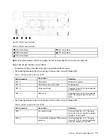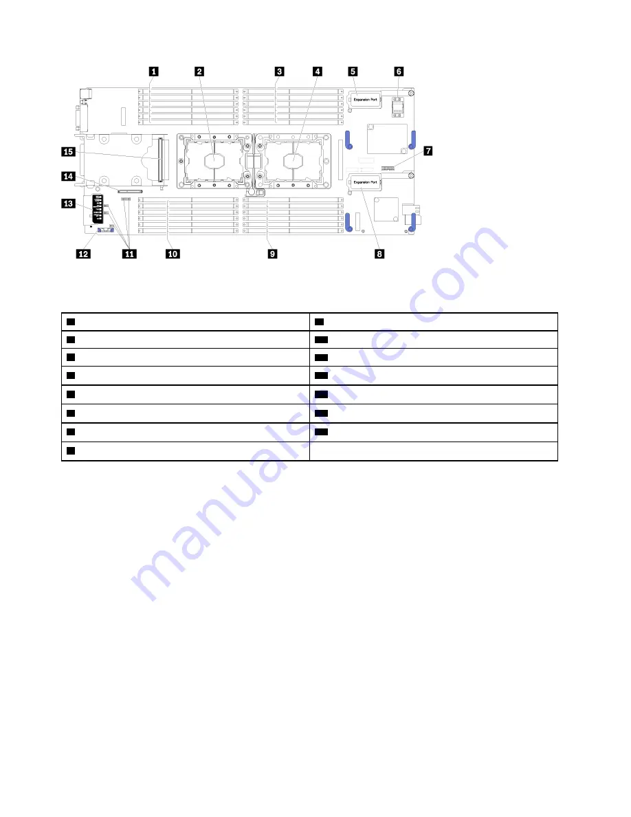
Figure 4. System-board connectors
Table 5. System-board connectors
1
DIMM slots 13–18
9
DIMM slots 7–12
2
Processor socket 2
10
DIMM slots 19–24
3
DIMM slots 1–6
11
Switch blocks
4
Processor socket 1
12
CMOS battery - CR2032
5
I/O expansion 1 connector
13
Light path diagnostics
6
Fabric connector socket
14
M.2 backplane connector
7
Trusted Cryptographic Module (TCM) connector
15
2.5-inch drive backplane connector
8
I/O expansion 2 connector
System-board switches
Use this information to locate the system-board switches.
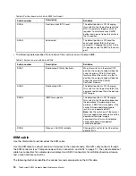
The following illustration shows the location of the switch blocks on the system board.
Important:
1. Before you change any switch settings or move any jumpers, turn off the compute node; then,
disconnect all power cords and external cables. Review the information in http://thinksystem.lenovofiles.
com/help/topic/safety_documentation/pdf_files.html, “Installation Guidelines” on page 21, “Handling
static-sensitive devices” on page 23, and “Power on the compute node” on page 8.
2. Any system-board switch or jumper block that is not shown in the illustrations in this document are
reserved.
14
ThinkSystem SN550 Compute Node Maintenance Manual
Summary of Contents for ThinkSystem SN550
Page 1: ...ThinkSystem SN550 Compute Node Maintenance Manual Machine Type 7X16 ...
Page 8: ...vi ThinkSystem SN550 Compute Node Maintenance Manual ...
Page 28: ...20 ThinkSystem SN550 Compute Node Maintenance Manual ...
Page 124: ...116 ThinkSystem SN550 Compute Node Maintenance Manual ...
Page 128: ...120 ThinkSystem SN550 Compute Node Maintenance Manual ...
Page 137: ......
Page 138: ...Part Number SP47A10572 Printed in China 1P P N SP47A10572 1PSP47A10572 ...


