background image

power button on the compute node does not respond until the power LED flashes slowly, indicating 
that the initialization process is complete.

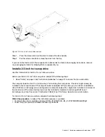
Step 5.  Turn on the compute node. 

Important: 

If an Attention label is on the front panel of the compute node above the power button, 

read it; then, remove the label and discard it before turning on the compute node.

Step 6.  Make sure that the power LED on the compute node control panel is lit continuously, indicating that 

the compute node is receiving power and is turned on.

Step 7.  If you have other compute nodes to install, do so now.

If this is the initial installation of the compute node in the chassis, you must configure the compute node 
through the Setup utility and install the compute node operating system. See the 

Setup Guide 

of the Lenovo 

ThinkSystem SN550 Type 7X16 compute node for details.

If you have changed the configuration of the compute node or if you are installing a different compute node 
from the one that you removed, you must configure the compute node through the Setup utility, and you 
might have to install the compute node operating system. See the 

Setup Guide 

of the Lenovo ThinkSystem 

SN550 Type 7X16 compute node for details..

•  For instructions related to the Flex System Enterprise chassis, see http://flexsystem.lenovofiles.com/help/ 

topic/com.lenovo.acc.8721.doc/installing_components.html.

•  For instructions related to the Flex System Carrier-Grade chassis, see http://flexsystem.lenovofiles.com/ 

help/topic/com.lenovo.acc.7385.doc/installing_components.html.

2.5-inch hot-swap drive replacement

Use the following information to remove and install a 2.5-inch hot-swap drive.

Remove a 2.5-inch hot-swap drive

Use this information to remove a 2.5-inch hot-swap drive.

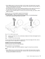
Before you remove a 2.5-inch hot-swap drive, complete the following steps: 

1.  Back up all important data before you make changes to the drives.

2.  Read “Safety” on page iii and “Installation Guidelines” on page 21 to ensure that you work safely.

3.  If one or more NVMe solid-state drives are to be removed, it is recommended to disable them 

beforehand via the operating system.

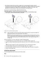
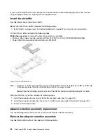
To remove a 2.5-inch hot-swap drive, complete the following steps:

Watch the procedure

. A video of the installation process is available: 

•  Youtube: https://www.youtube.com/playlist?list=PLYV5R7hVcs-B4_LYuT9X1MRWBU6UzX9gO
•  Youku: http://list.youku.com/albumlist/show/id_50481482

26

ThinkSystem SN550 Compute Node Maintenance Manual

Summary of Contents for ThinkSystem SN550

Page 1: ...ThinkSystem SN550 Compute Node Maintenance Manual Machine Type 7X16 ...

Page 2: ...ddition be sure that you are familiar with the terms and conditions of the Lenovo warranty for your server which can be found at http datacentersupport lenovo com warrantylookup Second Edition September 2017 Copyright Lenovo 2017 LIMITED AND RESTRICTED RIGHTS NOTICE If data or software is delivered pursuant to a General Services Administration GSA contract use reproduction or disclosure is subject...

Page 3: ...ter retention assembly 32 Install the adapter retention assembly 34 Bezel replacement 35 Remove the bezel 35 Install the bezel 36 Chassis bulkhead replacement 37 Remove the bulkhead 37 Install the bulkhead 39 CMOS battery CR2032 replacement 40 Remove the CMOS battery CR2032 40 Install the CMOS battery CR2032 41 Compute node cover replacement 42 Remove the compute node cover 42 Install the compute ...

Page 4: ...path diagnostics LEDs 99 System board LEDs 99 General problem determination procedures 100 Troubleshooting by symptom 101 Hard disk drive problems 101 Intermittent problems 102 Memory problems 103 Network problems 103 Observable problems 110 Optional device problems 111 Performance problems 113 Power on and power off problems 113 Software problems 114 Appendix A Getting help and technical assistan...

Page 5: ...ften Ennen kuin asennat tämän tuotteen lue turvaohjeet kohdasta Safety Information Avant d installer ce produit lisez les consignes de sécurité Vor der Installation dieses Produkts die Sicherheitshinweise lesen Prima di installare questo prodotto leggere le Informazioni sulla Sicurezza Les sikkerhetsinformasjonen Safety Information før du installerer dette produktet Antes de instalar este produto ...

Page 6: ... Check the power cord Make sure that the third wire ground connector is in good condition Use a meter to measure third wire ground continuity for 0 1 ohm or less between the external ground pin and the frame ground Make sure that the power cord is the correct type To view the power cords that are available for the server a Go to http lesc lenovo com b In the Customize a Model pane 1 Click Select O...

Page 7: ...6 Make sure that the power supply cover fasteners screws or rivets have not been removed or tampered with Copyright Lenovo 2017 v ...

Page 8: ...vi ThinkSystem SN550 Compute Node Maintenance Manual ...

Page 9: ...acentersupport lenovo com warrantylookup Notes 1 The first generation Chassis Management Module CMM1 68Y7030 is not supported by the ThinkSystem SN550 compute node 2 The second generation Chassis Management Module CMM2 00FJ669 must be at firmware level 1 6 1 or above to support the ThinkSystem SN550 compute node This applies to both CMMs that are installed in the chassis 3 The illustrations in thi...

Page 10: ...information such as firmware level administrator accounts and so forth Figure 2 Location of customer information tabs Specifications The following information is a summary of the features and specifications of the compute node Depending on the model some features might not be available or some specifications might not apply 2 ThinkSystem SN550 Compute Node Maintenance Manual ...

Page 11: ...pports up to two small form factor SFF drive bays Drive bay can be either SATA only SAS SATA or NVMe SATA depending on the model Supported 2 5 inch drives Serial Attached SCSI SAS Serial Advanced Technology Attachment SATA hot swap hard disk drives solid state drives Non Volatile Memory Express NVMe solid state drives M 2 drive backplane ThinkSystem M 2 with Mirroring Enablement Kit contains dual ...

Page 12: ...um dew point 24 C 75 F Shipment Storage 8 90 Particulate contamination Attention Airborne particulates and reactive gases acting alone or in combination with other environmental factors such as humidity or temperature might pose a risk to the server For information about the limits for particulates and gases see Particulate contamination on page 122 Notes Future support is planned for the single M...

Page 13: ...Xpress System Packs UXSPs UXSPs are bundled updates designed and tested to provide the interdependent level of functionality performance and compatibility UXSPs are server machine type specific and are built with firmware and device driver updates to support specific Windows Server Red Hat Enterprise Linux RHEL and SUSE Linux Enterprise Server SLES operating system distributions Machine type speci...

Page 14: ...ce Additional information about using Lenovo XClarity Provisioning Manager to update firmware is available at http sysmgt lenovofiles com help topic LXPM platform_update html Lenovo XClarity Controller If you need to install a specific update you can use the Lenovo XClarity Controller interface for a specific server Notes To perform an in band update through Windows or Linux the operating system d...

Page 15: ...http sysmgt lenovofiles com help topic com lenovo lxca doc update_fw html Configuring the LAN over USB interface manually To perform a firmware update through the operating system using Lenovo XClarity Essentials OneCLI the Lenovo XClarity Controller must be configured to use the LAN over USB interface The firmware update package attempts to perform the setup automatically if needed If the automat...

Page 16: ...ips Lenovo continually updates the support website with the latest tips and techniques that you can use to solve issues that you might have with your compute node These Tech Tips also called retain tips or service bulletins provide procedures to work around issues related to the operation of your compute node To find the Tech Tips available for your compute node 1 Go to http datacentersupport leno...

Page 17: ...power command and the CMM web interface to start automatically when power is restored For more information about the CMM power command see the Flex System Chassis Management Module Command Line Interface Reference Guide at http flexsystem lenovofiles com help topic com lenovo acc cmm doc cli_command_power html From the CMM web interface select Compute Nodes from the Chassis Management menu For mor...

Page 18: ... power button for more than four seconds to turn off the compute node Attention Pressing the power button for 4 seconds forces the operating system to shut down immediately Data loss is possible You can turn off the compute node through the CMM power command the CMM web interface and the Lenovo XClarity Administrator application if installed For more information about the CMM power command see the...

Page 19: ...ctivity LED green 7 Fault LED yellow 4 Drive status LED yellow 8 USB management button 1 USB 3 0 connector Connect a USB device to this USB 3 0 connector Note It is best practice to connect a USB device to the front of only one compute node at a time in each Lenovo Flex System chassis 2 KVM connector Connect the console breakout cable to this connector see KVM cable on page 16 for more information...

Page 20: ...gement Module Command Line Interface Reference Guide at http flexsystem lenovofiles com help topic com lenovo acc cmm doc cli_command_power html From the CMM web interface select Compute Nodes from the Chassis Management menu For more information see the Flex System Chassis Management Module User s Guide at http flexsystem lenovofiles com help topic com lenovo acc cmm doc cmm_user_guide html All f...

Page 21: ...tem Chassis Management Module User s Guide at http flexsystem lenovofiles com help topic com lenovo acc cmm doc cmm_user_guide html All fields and options are described in the CMM web interface online help For more information about the Lenovo XClarity Administrator application see https support lenovo com us en documents LNVO XCLARIT 7 Fault LED yellow When this yellow LED is lit it indicates tha...

Page 22: ...information to locate the system board switches The following illustration shows the location of the switch blocks on the system board Important 1 Before you change any switch settings or move any jumpers turn off the compute node then disconnect all power cords and external cables Review the information in http thinksystem lenovofiles com help topic safety_documentation pdf_files html Installatio...

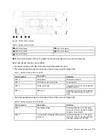
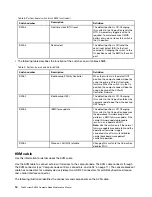
Page 23: ...very ME boots to recovery SW1 2 ME firmware security override For debug only SW1 3 Power permission Changing this switch to the on position enables Power On SW1 4 BMC reset Changing this switch to the on position forces the compute node to reset the BMC The following table describes the functions of the switches on switch block SW5 Table 8 System board switch block SW5 Switch number Description De...

Page 24: ...efault position is Off Changing this switch to the On position forces the compute node to boot from the backup UEFI image SW8 3 iBMC force update The default position is Off Changing this switch to the On position bypasses the operational firmware image and performs a BMC firmware update if the normal firmware update procedure results in an inoperative BMC Note Use this switch only if the normal f...

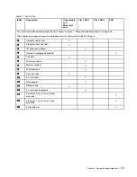
Page 25: ...t Use the parts list to identify each of the components that are available for your compute node For more information about ordering the parts shown in Figure 7 Compute node components on page 18 https datacentersupport lenovo com products servers thinksystem sn550 7x16 parts Note Depending on the model your compute node might look slightly different from the illustration Chapter 2 Compute node co...

Page 26: ...ay install a Tier 2 CRU yourself or request Lenovo to install it at no additional charge under the type of warranty service that is designated for your server Field replaceable unit FRU FRUs must be installed only by trained service technicians Consumable and Structural parts Purchase and replacement of consumable and structural parts components such as a cover or bezel is your responsibility If L...

Page 27: ... servers thinksystem sn550 7x16 parts 1 Compute node cover 2 Processor heat sink filler 3 I O expansion adapter 4 Trusted Cryptographic Module 5 Air baffle 6 Fabric connector 7 Memory module 8 M 2 backplane 9 Drive bay filler 10 2 5 inch drive 11 RAID adapter 12 Storage cage 13 2 5 inch drive backplane 14 Processor 2 heat sink and clip assembly 15 Processor 1 heat sink and clip assembly 16 System ...

Page 28: ...20 ThinkSystem SN550 Compute Node Maintenance Manual ...

Page 29: ...afety_documentation pdf_files html The following guidelines are available as well Handling static sensitive devices on page 23 and Working inside the server with the power on on page 22 Make sure the components you are installing are supported by the server For a list of supported optional components for the server see http www lenovo com serverproven When you install a new server download and app...

Page 30: ...system cooling and system reliability make sure that the following requirements are met Each of the drive bays has a drive or a filler panel and electromagnetic compatibility EMC shield installed in it Each of the power supply bays has a power supply or a filler installed in it If the server has redundant power each of the power supply bays has a power supply installed in it There is adequate spac...

Page 31: ...t least two seconds This drains static electricity from the package and from your body Remove the device from the package and install it directly into the server without putting it down If it is necessary to put the device down put it back into the static protective package Never place the device on the server or on any metal surface When handling a device carefully hold it by the edges or the fra...

Page 32: ... complete the following steps Watch the procedure A video of the installation process is available Youtube https www youtube com playlist list PLYV5R7hVcs B4_LYuT9X1MRWBU6UzX9gO Youku http list youku com albumlist show id_50481482 Figure 8 Compute node removal from chassis Step 1 Pull the front handle as shown in the illustration The compute node moves out of the node bay approximately 0 6 cm 0 25...

Page 33: ...igure 9 Compute node installation in chassis Step 1 Select the node bay Notes 1 If you are reinstalling a compute node that you removed you must install it in the same node bay from which you removed it Some compute node configuration information and update options are established according to node bay number Reinstalling a compute node into a different node bay can have unintended consequences If...

Page 34: ...See the Setup Guide of the Lenovo ThinkSystem SN550 Type 7X16 compute node for details For instructions related to the Flex System Enterprise chassis see http flexsystem lenovofiles com help topic com lenovo acc 8721 doc installing_components html For instructions related to the Flex System Carrier Grade chassis see http flexsystem lenovofiles com help topic com lenovo acc 7385 doc installing_comp...

Page 35: ...compute node has two 2 5 inch drive bays for installing hot swap drives One drive might already be installed in the compute node If the compute node is equipped with one drive you can install an additional drive RAID level 0 striping can be configured on a compute node with a single drive installed A minimum of two disk drives of the same interface type must be installed to implement and manage RA...

Page 36: ... the release lever Step 6 Check the drive status LEDs to make sure that the drive is operating correctly 2 5 inch drive backplane replacement Use the following information to remove and install a 2 5 inch drive backplane Remove the 2 5 inch drive backplane Use this information to remove the 2 5 inch drive backplane Before you remove the 2 5 inch drive backplane complete the following steps 1 Read ...

Page 37: ...9gO Youku http list youku com albumlist show id_50481482 Figure 12 2 5 inch drive backplane removal Step 1 Remove any drive bay fillers then pull the drives out slightly from the bays to disengage them from the backplane Step 2 Lift out the 2 5 inch drive backplane If you are instructed to return the component or optional device follow all packaging instructions and use any packaging materials for...

Page 38: ...fully seated in the connector Note All 2 5 inch drive backplanes use the same connector on the system board however there are two alignment slots in the storage cage to accommodate different backplane types Make sure that you align the backplane and system board connectors when inserting the backplane in the storage cage After you install the 2 5 inch drive backplane complete the following steps 1...

Page 39: ...mpute node with the bezel pointing toward you 5 Remove the compute node cover see Remove the compute node cover on page 42 To remove the air baffle complete the following steps Watch the procedure A video of the installation process is available Youtube https www youtube com playlist list PLYV5R7hVcs B4_LYuT9X1MRWBU6UzX9gO Youku http list youku com albumlist show id_50481482 Figure 14 Air baffle r...

Page 40: ...Figure 15 Air baffle installation Step 1 Align the air baffle pins with the pin holes on both sides of the chassis then lower the air baffle into the compute node Press the air baffle down until it is securely seated Note Close the retaining clip on each end of the DIMM connector before installing the air baffle After you install the air baffle complete the following steps 1 Install the compute no...

Page 41: ...e the adapter retention assembly complete the following steps Watch the procedure A video of the installation process is available Youtube https www youtube com playlist list PLYV5R7hVcs B4_LYuT9X1MRWBU6UzX9gO Youku http list youku com albumlist show id_50481482 Figure 16 Adapter retention assembly removal Step 1 Remove the air baffle see Remove the air baffle on page 31 Step 2 If necessary remove...

Page 42: ... 21 to ensure that you work safely The adapter retention assembly consists of 12 separate parts You can replace only the parts that you choose and save the unused parts for future use To install the adapter retention assembly complete the following steps Watch the procedure A video of the installation process is available Youtube https www youtube com playlist list PLYV5R7hVcs B4_LYuT9X1MRWBU6UzX9...

Page 43: ...5 Power on the compute node Bezel replacement Use the following information to remove and install the bezel Remove the bezel Use this information to remove the bezel Before you remove the bezel read safety information and guidelines to ensure that you work safely Read Safety on page iii and Installation Guidelines on page 21 to ensure that you work safely Power off the corresponding compute node t...

Page 44: ...or optional device follow all packaging instructions and use any packaging materials for shipping that are supplied to you Install the bezel Use this information to install the bezel Before you install the bezel read the safety information and guidelines to ensure that you work safely Read Safety on page iii and Installation Guidelines on page 21 to ensure that you work safely Note Several differe...

Page 45: ... is pressed flat against the chassis Lifting up slightly on the top edge of the bezel as you press it might make it easier to seat the clips Step 4 Install any removed storage drives or hard disk drive bay fillers see Install a 2 5 inch hot swap drive on page 27 Step 5 Close the front handle Chassis bulkhead replacement Use the following information to remove and install the chassis bulkhead Remov...

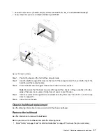
Page 46: ...Step 1 Remove the air baffle see Remove the air baffle on page 31 Step 2 Remove the fabric connector see Remove a fabric connector on page 49 Step 3 Remove the I O expansion adapters see Remove an I O expansion adapter on page 57 Step 4 Carefully place the compute node to the up side down orientation Step 5 Using a T8 Torx screwdriver remove the screws that secure the bulkhead from the bottom of t...

Page 47: ...3 Using a T8 Torx screwdriver install the screws that secure the bulkhead to the bottom of the compute node Step 4 Using a T8 Torx screwdriver install the screws that secure the bulkhead to the sides of the compute node Step 5 Carefully return the node to the bottom side down orientation After you install the bulkhead complete the following steps 1 Install the I O expansion adapters see Install an...

Page 48: ...low the following safety statement S004 CAUTION When replacing the lithium battery use only Lenovo specified part number or or an equivalent type battery recommended by the manufacturer If your system has a module containing a lithium battery replace it only with the same module type made by the same manufacturer The battery contains lithium and can explode if not properly used handled or disposed...

Page 49: ...compute node You must replace the CMOS battery CR2032 with a lithium CMOS battery CR2032 of the same type To order replacement batteries call 1 800 426 7378 within the United States and 1 800 465 7999 or 1 800 465 6666 within Canada Outside the U S and Canada call your Lenovo marketing representative or authorized reseller After you replace the CMOS battery CR2032 you must reconfigure the compute ...

Page 50: ... in the chassis on page 25 3 Power on the compute node Compute node cover replacement Use the following information to remove and install the compute node cover S012 CAUTION Hot surface nearby S021 CAUTION Hazardous energy is present when the blade is connected to the power source Always replace the blade cover before installing the blade Remove the compute node cover Use this information to remov...

Page 51: ...ging instructions and use any packaging materials for shipping that are supplied to you Install the compute node cover Use this information to install the compute node cover Before you install the compute node cover complete the following steps Watch the procedure A video of the installation process is available Youtube https www youtube com playlist list PLYV5R7hVcs B4_LYuT9X1MRWBU6UzX9gO Youku h...

Page 52: ... the chassis on page 25 2 Power on the compute node DIMM replacement Use the following information to remove and install a DIMM For DIMM configuration details see the Lenovo ThinkSystem SN550 Type 7X16 Setup Guide for more information Remove a DIMM Use this information to remove a DIMM Before you remove a DIMM complete the following steps 1 Read Safety on page iii and Installation Guidelines on pa...

Page 53: ...has changed Start the Setup utility and select Save Settings see the Lenovo ThinkSystem SN550 Type 7X16 Setup Guide for more information to save changes To remove a DIMM complete the following steps Watch the procedure A video of the installation process is available Youtube https www youtube com playlist list PLYV5R7hVcs B4_LYuT9X1MRWBU6UzX9gO Youku http list youku com albumlist show id_50481482 ...

Page 54: ...th retaining clips on the DIMM connector from which you are removing the DIMM are in the fully open position then pull the DIMM out of the connector Figure 27 DIMM removal Attention To maintain proper system cooling do not operate the compute node without an air baffle installed over the DIMM connectors Notes If you are not immediately replacing the DIMM install the air baffle see Install the air ...

Page 55: ...ket 1 2 Processor socket 2 5 DIMM connectors 7 12 3 DIMM connectors 1 6 6 DIMM connectors 19 24 To install a DIMM complete the following steps Watch the procedure A video of the installation process is available Youtube https www youtube com playlist list PLYV5R7hVcs B4_LYuT9X1MRWBU6UzX9gO Youku http list youku com albumlist show id_50481482 Attention Memory modules are sensitive to static dischar...

Page 56: ...ve devices The package must be grounded before it is opened To avoid breaking the retaining clips or damaging the DIMM connector handle the clips gently Figure 29 Opening retaining clip Notes If necessary due to space constraints you can use a pointed tool to open the retaining clips Place the tip of the tool in the recess on the top of the retaining clip then carefully rotate the retaining clip a...

Page 57: ...ver on page 43 3 Install the compute node into the chassis see Install the compute node in the chassis on page 25 4 Power on the compute node Fabric connector replacement Use the following information to remove and install a fabric connector Remove a fabric connector Use this information to remove a fabric connector Before you remove the fabric connector complete the following steps 1 Read Safety ...

Page 58: ...ift the fabric connector from the system board and store it in a safe place If you are instructed to return the component or optional device follow all packaging instructions and use any packaging materials for shipping that are supplied to you If you have removed the fabric connector to install an I O expansion adapter in I O expansion connector 1 keep the fabric connector in a safe place for fut...

Page 59: ...ll the compute node into the chassis see Install the compute node in the chassis on page 25 3 Power on the compute node Flash power module replacement Use the following information to remove and install the flash power module Remove the flash power module Use this information to remove the flash power module Before you remove the flash power module complete the following steps 1 Read Safety on pag...

Page 60: ...e flash power module cable or connector it is important to first slide out the flash power module This provides more space for your fingers to better grip the flash power module cable and remove it from the connector If you are instructed to return the component or optional device follow all packaging instructions and use any packaging materials for shipping that are supplied to you Install the fl...

Page 61: ...tching on the DIMM connector latches when the RAID adapter is installed in a ThinkSystem node After you install the flash power module complete the following steps 1 Install the RAID adapter in the compute node see Install a RAID adapter on page 79 2 Install the compute node cover see Install the compute node cover on page 43 3 Install the compute node into the chassis see Install the compute node...

Page 62: ...component or optional device follow all packaging instructions and use any packaging materials for shipping that are supplied to you Install the front handle Use this information to install the front handle Before you install the front handle 1 Read Safety on page iii and Installation Guidelines on page 21 to ensure that you work safely To install the front handle complete the following steps Watc...

Page 63: ... label plate Use this information to remove the identification ID label plate from the front panel Before you remove the ID label plate read 1 Read Safety on page iii and Installation Guidelines on page 21 to ensure that you work safely To remove the ID label plate complete the following steps Watch the procedure A video of the installation process is available Youtube https www youtube com playli...

Page 64: ... shipping that are supplied to you Install the ID label plate Use this information to install the identification ID label plate on the front panel Before you install the ID label plate read 1 Read Safety on page iii and Installation Guidelines on page 21 to ensure that you work safely To install the ID label plate complete the following steps Watch the procedure A video of the installation process...

Page 65: ...on to remove an I O expansion adapter Before you remove the I O expansion adapter complete the following steps 1 Read Safety on page iii and Installation Guidelines on page 21 to ensure that you work safely 2 Power off the corresponding compute node that you are going to perform the task on 3 Remove the compute node from the chassis see Remove the compute node from the chassis on page 24 4 Careful...

Page 66: ...expansion adapter Before you install an I O expansion adapter complete the following steps 1 Read Safety on page iii and Installation Guidelines on page 21 to ensure that you work safely This component can be installed as an optional device or as a CRU The installation procedure is the same for the optional device and the CRU The optional Flex System PCIe Expansion Node supports additional PCIe ad...

Page 67: ...n connector To install an I O expansion adapter complete the following steps Watch the procedure A video of the installation process is available Youtube https www youtube com playlist list PLYV5R7hVcs B4_LYuT9X1MRWBU6UzX9gO Youku http list youku com albumlist show id_50481482 Chapter 3 Hardware replacement procedures 59 ...

Page 68: ...mplete the following steps 1 Install the compute node cover see Install the compute node cover on page 43 2 Install the compute node into the chassis see Install the compute node in the chassis on page 25 3 Power on the compute node 4 See the documentation that comes with the expansion adapter for device driver and configuration information to complete the installation M 2 backplane replacement Us...

Page 69: ... 2 drive from the M 2 backplane see Remove an M 2 drive on page 62 If you are instructed to return the component or optional device follow all packaging instructions and use any packaging materials for shipping that are supplied to you Install the M 2 backplane Use this information to install the M 2 backplane Before you install the M 2 backplane complete the following steps 1 Read Safety on page ...

Page 70: ...M 2 backplane for device driver and configuration information to complete the installation M 2 drive replacement Use the following information to remove and install an M 2 drive Remove an M 2 drive Use this information to remove an M 2 drive from the M 2 backplane Before you remove an M 2 drive from the M 2 backplane complete the following steps 1 Read Safety on page iii and Installation Guideline...

Page 71: ...adjust the position of the retainer on the M 2 backplane complete the following steps 1 Read Safety on page iii and Installation Guidelines on page 21 to ensure that you work safely To adjust the position of the retainer on the M 2 backplane complete the following steps Watch the procedure A video of the installation process is available Youtube https www youtube com playlist list PLYV5R7hVcs B4_L...

Page 72: ...modate the particular size of the M 2 drive you wish to install see Adjust the position of the retainer on the M 2 backplane on page 63 To install an M 2 drive in the M 2 backplane complete the following steps Watch the procedure A video of the installation process is available Youtube https www youtube com playlist list PLYV5R7hVcs B4_LYuT9X1MRWBU6UzX9gO Youku http list youku com albumlist show i...

Page 73: ...n the retainer enter the small holes on the M 2 backplane Once they enter the holes you will hear a soft click sound Figure 49 M 2 drive installation After you install an M 2 drive in the M 2 backplane complete the following steps 1 Install the M 2 backplane see Install the M 2 backplane on page 61 2 Install the compute node cover see Install the compute node cover on page 43 3 Install the compute...

Page 74: ... T30 driver Attention Each processor socket must always contain a cover or a PHM When removing or installing a PHM protect empty processor sockets with a cover Do not touch the processor socket or processor contacts Processor socket contacts are very fragile and easily damaged Contaminants on the processor contacts such as oil from your skin can cause connection failures Remove and install only on...

Page 75: ... and processor location Table 14 DIMM and processor location 1 DIMM connectors 13 18 4 Processor socket 1 2 Processor socket 2 5 DIMM connectors 7 12 3 DIMM connectors 1 6 6 DIMM connectors 19 24 Complete the following steps to remove a PHM Watch the procedure A video of the installation process is available Youtube https www youtube com playlist list PLYV5R7hVcs B4_LYuT9X1MRWBU6UzX9gO Youku http ...

Page 76: ...sink module in the removal sequence shown on the heat sink label b Lift the processor heat sink module from the processor socket After you remove a PHM If you are removing the PHM as part of a system board replacement set the PHM aside If you are replacing the processor or heat sink separate the processor and its retainer from the heat sink 68 ThinkSystem SN550 Compute Node Maintenance Manual ...

Page 77: ...ide down and the processor contact side up to prevent the processor from falling out of the retainer Note The processor retainer will be removed and discarded in a later step and replaced with a new one If you are replacing the processor you will be reusing the heat sink Wipe the thermal grease from the bottom of the heat sink using an alcohol cleaning pad If you are replacing the heat sink you wi...

Page 78: ... firmware in the ThinkSystem SN550 Setup Guide Installing an additional PHM can change the memory requirements for your system See Install a DIMM in the ThinkSystem SN550 Setup Guide for a list of processor to memory relationships Optional devices available for you system might have specific processor requirements See the documentation that comes with the optional device for information Before you...

Page 79: ...ssor retainer Figure 54 Installing a processor retainer 1 Position the processor on the new retainer so that the triangular marks align then insert the unmarked end of the processor into the retainer 2 Holding the inserted end of the processor in place flex the opposite end of the retainer down and away from the processor until you can press the processor under the clip on the retainer To prevent ...

Page 80: ...r of the processor top 9 If you are replacing a heat sink remove the processor identification label from the old heat sink and place it on the new heat sink in the same location The label is on the side of the heat sink closet to the triangular alignment mark If you are unable to remove the label and place it on the new heat sink or if the label is damaged during transfer write the processor seria...

Page 81: ...or align the triangular mark on the processor retainer with the notched corner of the heat sink b Insert the processor retainer clips into the holes on the heat sink c Press the retainer into place until the clips at all four corners engage Figure 57 DIMM and processor location Chapter 3 Hardware replacement procedures 73 ...

Page 82: ...processor socket Attention To prevent damage to components make sure that you follow the indicated tightening sequence b Fully tighten the Torx T30 captive fasteners in the installation sequence shown on the heat sink label Tighten the screws until they stop then visually inspect to make sure that there is no gap between the screw shoulder beneath the heat sink and the processor socket For referen...

Page 83: ...ove the RFID tag read 1 Read Safety on page iii and Installation Guidelines on page 21 to ensure that you work safely To remove the RFID tag complete the following steps Watch the procedure A video of the installation process is available Youtube https www youtube com playlist list PLYV5R7hVcs B4_LYuT9X1MRWBU6UzX9gO Youku http list youku com albumlist show id_50481482 Chapter 3 Hardware replacemen...

Page 84: ...he RFID tag from the ID label plate on the front panel of the compute node Hold the ID label plate in place on the compute node front panel while removing the RFID tag If you are instructed to return the component or optional device follow all packaging instructions and use any packaging materials for shipping that are supplied to you Install the RFID tag Use this information to install the RFID t...

Page 85: ...ow id_50481482 Figure 60 RFID tag installation Step 1 Make sure that the surface you are installing the tag on is thoroughly clean and dry Step 2 Open the RFID tag then remove the backing from the base of the RFID tag to expose the adhesive Step 3 Position the RFID tag over the ID label on the front panel of the compute node Step 4 Press the RFID tag securely against the bezel and hold firmly in p...

Page 86: ...ge 42 The RAID adapter uses a specific drive backplane If you need to remove the RAID adapter to access components on the system board for example DIMM sockets 13 24 there is no need to remove the backplane If you are removing only the RAID adapter to replace it there is no need to remove the backplane To remove the RAID adapter complete the following steps Watch the procedure A video of the insta...

Page 87: ...owever there are two alignment slots in the drive cage to accommodate different backplane types Make sure that you align the backplane and system board connectors when inserting the backplane in the drive cage Step 2 If you are installing both the RAID adapter and drive backplane first install the backplane in the system board assembly see Install a 2 5 inch drive backplane on page 29 The drive ba...

Page 88: ...ves and drive bay fillers see Install a 2 5 inch hot swap drive on page 27 Note Install storage drives in the same bay locations as from which they were removed 2 Install the compute node cover see Install the compute node cover on page 43 3 Install the compute node into the chassis see Install the compute node in the chassis on page 25 4 Power on the compute node 5 Configure the RAID array 80 Thi...

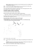
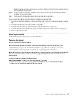
Page 89: ...ng steps Watch the procedure A video of the installation process is available Youtube https www youtube com playlist list PLYV5R7hVcs B4_LYuT9X1MRWBU6UzX9gO Youku http list youku com albumlist show id_50481482 Figure 65 Storage cage removal Step 1 Remove the bezel see Remove the bezel on page 35 Step 2 Remove any storage drives optional drive components and drive bay fillers and set them aside on ...

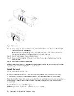
Page 90: ...3 Using a T10 Torx screwdriver insert the four screws and secure the cage in the compute node After you install the storage cage complete the following steps 1 Install the 2 5 drive backplane see Install a 2 5 inch drive backplane on page 29 2 Install the bezel see Install the bezel on page 36 3 Install any removed storage drives optional drive components and drive bay fillers see Install a 2 5 in...

Page 91: ...ernal component in the replacement system board assembly immediately after removing it from the defective system board assembly Step 1 Remove any storage drives optional drive components and hard disk drive bay fillers from the defective system board assembly and set them aside on a static protective surface see Remove a 2 5 inch hot swap drive on page 26 Notes When removing the storage drives mak...

Page 92: ...t from the defective system board assembly then immediately install them on the replacement system board assembly I O expansion adapters and other optional components See procedures such as Remove an I O expansion adapter on page 57 and Install an I O expansion adapter on page 58 Step 13 If a RAID adapter was removed from the defective system board assembly install it in the replacement system boa...

Page 93: ...om of replacement system board assembly Figure 67 Repair Identification RID tag After you transfer components to the replacement system board assembly complete the following steps 1 Install the compute node in the chassis see Install the compute node in the chassis on page 25 2 If an Attention label is on the replacement system board assembly front panel above the power button read it then remove ...

Page 94: ...tem board assembly that you are returning prior to shipment Use the heat sink fillers that were removed from the replacement system board assembly when you installed the processors Do not install the processor socket dust covers in the defective system board assembly that you are returning Update the Universal Unique Identifier UUID The Universal Unique Identifier UUID must be updated when the sys...

Page 95: ...face which requires that the IPMI driver be installed Remote LAN access type the command Note When using the remote LAN access method to access Lenovo XClarity Controller using the LAN from a client the host and the bmc_external_ip address are required parameters bmc bmc_user_id bmc_password bmc_externaln _ip Where bmc_external_ip The external BMC Lenovo XClarity Controller LAN IP address There is...

Page 96: ...e style KCS access Remote access to the target system LAN based Step 1 After you haveLenovo XClarity Essentials OneCLI in place type the following commands to set the DMI onecli config set SYSTEM_PROD_DATA SysInfoProdName m t_model access_method onecli config set SYSTEM_PROD_DATA SysInfoSerialNum s n access_method onecli config set SYSTEM_PROD_DATA SysEncloseAssetTag asset_tag access_method Where ...

Page 97: ...ssetTag asset_tag Remote LAN access type the command Note When using the remote LAN access method to access Lenovo XClarity Controller using the LAN from a client the host and the bmc_external_ip address are required parameters bmc bmc_user_id bmc_password bmc_external_ip Where bmc_external_ip The external BMC Lenovo XClarity Controller LAN IP address There is no default value This parameter is re...

Page 98: ...l Presence Before you can assert Physical Presence the Physical Presence Policy must be enabled By default the Physical Presence Policy is enabled with a timeout of 30 minutes If the Physical Presence Policy is enabled you can assert Physical Presence through the Lenovo XClarity Controller or through hardware jumpers on the system board Notes If the Physical Presence Policy has been disabled 1 Set...

Page 99: ...pdate to TPM1 2 compliant bmc userid password ip_address where userid password are the credentials used to access the BMC Lenovo XClarity Controller interface of your server The default user ID is USERID and the default password is PASSW0RD zero not an uppercase o ip_address is the IP address of the BMC For more information about the Lenovo XClarity Essentials OneCLI s se et t command see http sys...

Page 100: ...nfiguration SecureBootSetting Enabled override bmc userid password ip_address where userid password are the credentials used to access the BMC Lenovo XClarity Controller interface of your server The default user ID is USERID and the default password is PASSW0RD zero not an uppercase o ip_address is the IP address of the BMC For more information about the Lenovo XClarity Essentials OneCLI s se et t...

Page 101: ...e 57 as it will block your access to the TCM connector Step 3 Carefully hold the TCM by its edges then gently press on the latch and lift it from the system board If you are instructed to return the component or optional device follow all packaging instructions and use any packaging materials for shipping that are supplied to you Install the Trusted Cryptographic Module TCM Use this information to...

Page 102: ...ouch the static protective package that contains the TCM to any unpainted metal surface on the Lenovo Flex System chassis or any unpainted metal surface on any other grounded rack component then remove the TCM from the package Step 4 Carefully hold the TCM by its edges and insert it into the TCM connector on the system board After you install the TCM complete the following steps 1 Install the comp...

Page 103: ...e begin with the Chassis Management Module event log If you are using some other management application begin with the Lenovo XClarity Controller event log Event logs An alert is a message or other indication that signals an event or an impending event Alerts are generated by the Lenovo XClarity Controller or by UEFI in the servers These alerts are stored in the Lenovo XClarity Controller Event Lo...

Page 104: ...e chassis including switch modules compute nodes fans and power supplies Figure 71 CMM event log For more information about accessing the CMM event log see http flexsystem lenovofiles com help topic com lenovo acc cmm doc cmm_ui_events html Lenovo XClarity Controller event log The Lenovo XClarity Controller monitors the physical state of the server and its components using sensors that measure int...

Page 105: ...og html Light path diagnostics Use this information as an overview of light path diagnostics Light path diagnostics is a system of LEDs above the control panel and on various internal components of the compute node When an error occurs LEDs can be lit throughout the compute node to help identify the source of the error Viewing the light path diagnostics LEDs Use this information to locate and iden...

Page 106: ... com help topic com lenovo acc cmm doc cli_command_led html From the CMM web interface select Compute Nodes from the Chassis Management menu For more information see the Flex System Chassis Management Module User s Guide at http flexsystem lenovofiles com help topic com lenovo acc cmm doc cmm_user_guide html All fields and options are described in the CMM web interface online help For more informa...

Page 107: ...on about error conditions is in the CMM event log Table 17 Light path diagnostics LEDs Light path diagnostics LED Description Light path diagnostics The power source for the light path diagnostics LEDs is charged System board The system board has failed NMI The system board has failed CPU Mismatch The processors are mismatched Temperature The system temperature has exceeded a threshold level Memor...

Page 108: ...t contain specific errors or the compute node is inoperative If you are not sure about the cause of a problem and the power supplies are working correctly complete the following steps to attempt to resolve the problem 1 Power off the compute node 2 Make sure that the compute node is cabled correctly 3 Remove or disconnect the following devices one at a time until you find the failure Power on and ...

Page 109: ...om the Chassis Management Module begin with the Chassis Management Module event log If you are using some other management application begin with the Lenovo XClarity Controller event log For more information about event logs see Event logs on page 95 2 Review this section to find the symptoms that you are experiencing and follow the suggested actions to resolve the issue 3 If the problem persists ...

Page 110: ...y to the compute node Make sure that the device is configured correctly for the port Intermittent KVM problems Complete the following steps until the problem is solved Video problems 1 Make sure that all cables and the console breakout cable are properly connected and secure 2 Make sure that the monitor is working properly by testing it on another compute node 3 Test the console breakout cable on ...

Page 111: ...it detected a problem or a DIMM might have been manually disabled To determine the status of a DIMM restart the compute node and press F1 to display theLenovo XClarity Provisioning Manager interface Then click System settings Memory 5 Run memory diagnostics When you start a compute node and press F1 the Lenovo XClarity Provisioning Manager interface is displayed by default You can perform memory d...

Page 112: ...bled By default only secure protocols are enabled for example SSH and HTTPS 3 Make sure that you can log into the CMM If you are unable to log in to the CMM see Cannot log in to CMM on page 103 4 Reset the CMM to the default settings by pressing the reset button on the CMM Press and hold the button for 10 seconds to reset the CMM configuration settings All user modified configuration settings are ...

Page 113: ...nd secure and that the activity LEDs are lit on the appropriate ports 3 From the compute node operating system verify the network settings such as IP address subnet mask if using IPv4 DHCP settings and vLAN settings to ensure that the settings match the settings of the network device See the documentation for the operating system for information about checking network settings 4 From the compute n...

Page 114: ...ay to see if the problem persists See Installing a compute node in a chassis If the problem persists make sure that this compute node is connected to a port that has been enabled and that the vLAN settings enable that port to connect to the network 8 Check the Lenovo support Web site for any service bulletins that are related to network connectivity 9 Trained service technician only Perform the fo...

Page 115: ...bent contact Lenovo Support 6 Install the compute node in another node bay to determine whether the problem remains If the problem remains make sure that the compute node is connected to a port that has been enabled and that the vLAN settings allow that port to connect to the network 7 Check http datacentersupport lenovo com for any tech tips service bulletins that are related to network connectiv...

Page 116: ...e same subnet 2 Verify that the cables between the CMMs and the top of rack switch are correctly connected and that the activity LEDs are lit on the applicable ports 3 Make sure that the management node has a correct IP address and is on the same subnet as the CMMs 4 Make sure that the compute node BMC has acquired an IP address from the CMM by using the Setup utility on the node Note If the CMM r...

Page 117: ...ule to make sure that no pins are bent c Check the connectors on the chassis midplane to make sure that no pins are bent d Remove the I O module and install a working I O module in the same I O bay e If the problem is solved replace the I O module that you removed Multiple compute nodes cannot ping an I O module Complete the following steps until the problem is solved 1 If you have recently update...

Page 118: ...rrectly 4 Trained technician only Remove processor 2 and restart the compute node 5 Replace the following components one at a time in the order shown restarting the compute node each time a Trained technician only Processor b Trained technician only System board Compute node is unresponsive POST is complete and operating system is running Complete the following steps until the problem is solved If...

Page 119: ...not restart suspect the system board Unusual smell Complete the following steps until the problem is solved 1 An unusual smell might be coming from newly installed equipment 2 If the problem remains contact Lenovo Support Compute node seems to be running hot Complete the following steps until the problem is solved Multiple compute nodes or chassis 1 Make sure that the room temperature is within th...

Page 120: ...e problem is resolved 1 Remove one of the PCIe adapters 2 Restart the system and press F1 to display the Lenovo XClarity Provisioning Manager system setup interface 3 Click UEFI Setup System Settings Devices and I O Ports MM Config Base then modify the setting to the lower memory capacity For example modify 3 GB to 2 GB or modify 2 GB to 1 GB 4 Save the settings and restart the system 5 The action...

Page 121: ...e updated device drivers or installed software applications remove the changes 2 Check for any networking issues 3 Check the operating system logs for performance related errors 4 Check for events related to high temperatures and power issues as the compute node might be throttled to help with cooling If it is throttled reduce the workload on the compute node to help improve performance 5 Check fo...

Page 122: ...mpt to power on the compute node from the CMM Multiple compute nodes do not power on Complete the following steps until the problem is resolved 1 If you recently installed moved or serviced the computer nodes reseat the compute nodes in the bays If the compute nodes were not recently installed moved or serviced perform a virtual reseat through the CMM service command For more information about the...

Page 123: ... node Other software works on the compute node The software works on another compute node 2 If you receive any error messages while you use the software see the information that comes with the software for a description of the messages and suggested solutions to the problem 3 Contact your place of purchase of the software Chapter 4 Problem determination 115 ...

Page 124: ...116 ThinkSystem SN550 Compute Node Maintenance Manual ...

Page 125: ...System products at the following location http thinksystem lenovofiles com help index jsp You can take these steps to try to solve the problem yourself Check all cables to make sure that they are connected Check the power switches to make sure that the system and any optional devices are turned on Check for updated software firmware and operating system device drivers for your Lenovo product The L...

Page 126: ...ion as soon as you have completed and submitted an Electronic Service Request Collecting service data To clearly identify the root cause of a server issue or at the request of Lenovo Support you might need collect service data that can be used for further analysis Service data includes information such as event logs and hardware inventory Service data can be collected through the following tools L...

Page 127: ...in nf fo or r command For more information about running the g ge et tiin nf fo or r see http sysmgt lenovofiles com help topic toolsctr_cli_lenovo onecli_r_getinfor_command html Contacting Support You can contact Support to obtain help for your issue You can receive hardware service through a Lenovo Authorized Service Provider To locate a service provider authorized by Lenovo to provide warranty ...

Page 128: ...120 ThinkSystem SN550 Compute Node Maintenance Manual ...

Page 129: ...n new editions of the publication Lenovo may make improvements and or changes in the product s and or the program s described in this publication at any time without notice The products described in this document are not intended for use in implantation or other life support applications where malfunction may result in injury or death to persons The information contained in this document does not ...

Page 130: ... hard disk drives and population of all hard disk drive bays with the largest currently supported drives that are available from Lenovo Maximum memory might require replacement of the standard memory with an optional memory module Each solid state memory cell has an intrinsic finite number of write cycles that the cell can incur Therefore a solid state device has a maximum number of write cycles t...

Page 131: ...fficiency or greater using high efficiency particulate air HEPA filters that meet MIL STD 282 The deliquescent relative humidity of the particulate contamination must be more than 60 2 The room must be free of conductive contamination such as zinc whiskers Gaseous Copper Class G1 as per ANSI ISA 71 04 19853 Silver Corrosion rate of less than 300 Å in 30 days 1 ASHRAE 52 2 2008 Method of Testing Ge...

Page 132: ...Taiwan BSMI RoHS declaration Taiwan import and export contact information Contacts are available for Taiwan import and export information 124 ThinkSystem SN550 Compute Node Maintenance Manual ...

Page 133: ...ystem board 13 contamination particulate and gaseous 122 cover installing 43 removing 42 replacing 42 CPU installing 70 removing 66 replacing 66 creating a personalized support web page 117 custom support web page 117 D device returning 23 devices static sensitive handling 23 DIMM removing 44 replacing 44 47 DIMM connectors 13 Drive status LED 11 E enable TPM 89 F fabric connector location 13 remo...

Page 134: ...ng 97 light path diagnostics 97 light path diagnostics panel 99 light path diagnostics viewing 97 M M 2 backplane removing 60 replacing 60 61 M 2 drive removing 62 replacing 62 64 memory problems 103 memory module replacing 44 microprocessor removing 66 replacing 66 microprocessor connector 13 microprocessor heat sink module removing 66 replacing 66 N network problems 103 node bay filler 25 notes ...

Page 135: ...sor 66 processor heat sink module 66 RAID adapter 78 79 RFID tag 75 76 storage cage 81 82 system board assembly 82 Trusted Cryptographic Module TCM 92 93 retainer on M 2 backplane adjustment 63 returning a device or component 23 RFID tag removing 75 replacing 75 76 S safety iii safety inspection checklist iv Secure Boot 91 security advisories 8 service and support before you call 117 hardware 119 ...

Page 136: ...raphic Module 89 Trusted Cryptographic Module TCM removing 92 replacing 92 93 Trusted Platform Module 89 turning off the compute node 10 turning on the compute node 8 U UEFI Secure Boot 91 update firmware 4 updating configuration 23 DMI SMBIOS 88 Universal Unique Identifier UUID 86 USB management button 11 W Windows driver LAN over USB 7 working inside the server power on 22 128 ThinkSystem SN550 ...

Page 137: ......

Page 138: ...Part Number SP47A10572 Printed in China 1P P N SP47A10572 1PSP47A10572 ...

Reviews: