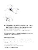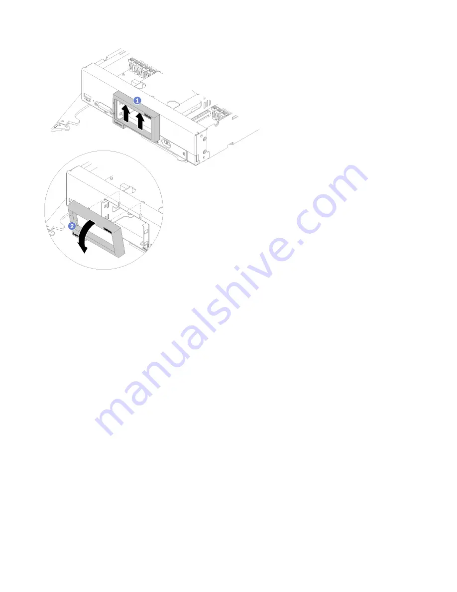
Figure 18. Bezel removal
Step 1. If any storage drives or hard disk drive bay fillers are installed, remove them (see “Remove a 2.5-
inch hot-swap drive” on page 26 ).
Note:
When removing the storage drives, make note of the drive bay from which the drive was
removed so that you can install the drive back in to the same drive bay.
Step 2. Pull the front handle as shown in the illustration.
Step 3. Press up on the inside top of the bezel; then, rotate the top edge of the bezel away from the
compute node.
Step 4. Lift the bezel from the compute node.
If you are instructed to return the component or optional device, follow all packaging instructions, and use
any packaging materials for shipping that are supplied to you.
Install the bezel
Use this information to install the bezel.
Before you install the bezel, read the safety information and guidelines to ensure that you work safely.
• Read “Safety” on page iii and “Installation Guidelines” on page 21 to ensure that you work safely.
Note:
Several different types of bezel can be installed in the compute node: all are removed and installed in a
similar manner. The bezel shown in the illustrations might differ slightly from the bezel installed in your
compute node.
To install the bezel, complete the following steps:
Watch the procedure
. A video of the installation process is available:
36
ThinkSystem SN550 Compute Node Maintenance Manual
Summary of Contents for ThinkSystem SN550
Page 1: ...ThinkSystem SN550 Compute Node Maintenance Manual Machine Type 7X16 ...
Page 8: ...vi ThinkSystem SN550 Compute Node Maintenance Manual ...
Page 28: ...20 ThinkSystem SN550 Compute Node Maintenance Manual ...
Page 124: ...116 ThinkSystem SN550 Compute Node Maintenance Manual ...
Page 128: ...120 ThinkSystem SN550 Compute Node Maintenance Manual ...
Page 137: ......
Page 138: ...Part Number SP47A10572 Printed in China 1P P N SP47A10572 1PSP47A10572 ...

