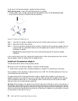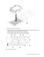
To remove an I/O expansion adapter, complete the following steps:
Watch the procedure
. A video of the installation process is available:
• Youtube: https://www.youtube.com/playlist?list=PLYV5R7hVcs-B4_LYuT9X1MRWBU6UzX9gO
• Youku: http://list.youku.com/albumlist/show/id_50481482
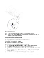
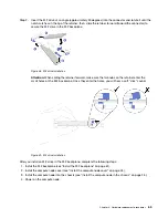
Figure 39. I/O expansion adapter removal
Step 1. Locate the I/O expansion adapter connectors (see “System-board connectors” on page 13 ).
Step 2. Rotate the retention clips outward.
Step 3. Lift the I/O expansion adapter from the connector and remove the I/O expansion adapter from the
compute node. You might find it helpful to rock the adapter back and forth, from front to rear, to
disengage the adapter.
Important:
Rocking the adapter from side to side might damage the I/O expansion adapter
connector.
If you are instructed to return the component or optional device, follow all packaging instructions, and use
any packaging materials for shipping that are supplied to you.
Install an I/O expansion adapter
Use this information to install an I/O expansion adapter.
Before you install an I/O expansion adapter, complete the following steps:
1. Read “Safety” on page iii and “Installation Guidelines” on page 21 to ensure that you work safely.
This component can be installed as an optional device or as a CRU. The installation procedure is the same
for the optional device and the CRU.
The optional Flex System PCIe Expansion Node supports additional PCIe adapters and I/O expansion
adapters to provide a cost-effective way for you to increase and customize the capabilities of the compute
node. For additional information, see "PCIe Expansion Node" at http://flexsystem.lenovofiles.com/help/
topic/com.lenovo.acc.pme.doc/product_page.html.
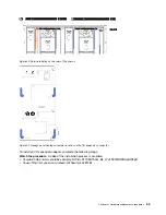
Attention:
When installing an I/O adapter in one of the I/O expansion connectors, make sure the numbers in
the Hexagon and Pentagon on the I/O expansion connector (see the service labeling on top of the compute
node cover for details) corresponds to the particular shape and numbering of the I/O module bay on the Flex
chassis (see the service labeling at the top on the rear of the chassis for details). If the correlation is incorrect,
communication with the chassis may fail.
58
ThinkSystem SN550 Compute Node Maintenance Manual
Summary of Contents for ThinkSystem SN550
Page 1: ...ThinkSystem SN550 Compute Node Maintenance Manual Machine Type 7X16 ...
Page 8: ...vi ThinkSystem SN550 Compute Node Maintenance Manual ...
Page 28: ...20 ThinkSystem SN550 Compute Node Maintenance Manual ...
Page 124: ...116 ThinkSystem SN550 Compute Node Maintenance Manual ...
Page 128: ...120 ThinkSystem SN550 Compute Node Maintenance Manual ...
Page 137: ......
Page 138: ...Part Number SP47A10572 Printed in China 1P P N SP47A10572 1PSP47A10572 ...


