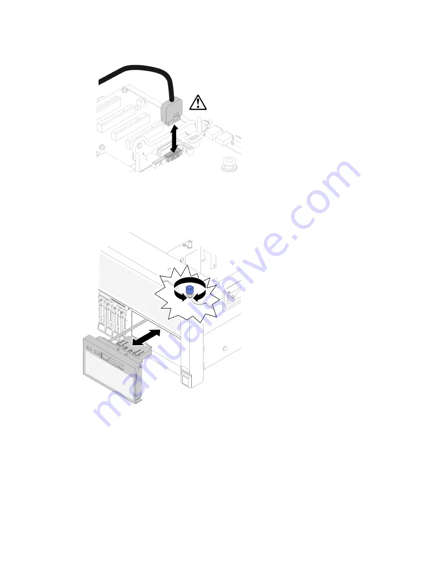
Figure 84. Removing USB 3.0 connector vertically
Step 3. Remove the USB 3.0 cable from the cable guide.
Step 4. Loosen the screw that secures the tray assembly.
Step 5. Push the tray assembly slightly out of the server; then; grasp it from the front and pull it out from the
server.
Figure 85. Operator panel tray assembly removal
If you are instructed to return the component or optional device, follow all packaging instructions, and use
any packaging materials for shipping that are supplied to you.
Install the operator panel tray assembly
Use this procedure to install the operator panel tray assembly.
Before installing the operator panel tray assembly:
1. Read the safety information and installation guidelines (see “Safety” on page iii and “Installation
.
Hardware replacement procedures
93
Summary of Contents for ThinkSystem SR860
Page 1: ...ThinkSystem SR860 Maintenance Manual Machine Type 7X69 7X70 ...
Page 8: ...vi ThinkSystem SR860 Maintenance Manual ...
Page 63: ...Figure 48 Server components Chapter 2 Server components 55 ...
Page 200: ...192 ThinkSystem SR860 Maintenance Manual ...
Page 210: ...202 ThinkSystem SR860 Maintenance Manual ...
Page 211: ......
Page 212: ...Part Number SP47A30805 Printed in China 1P P N SP47A30805 1PSP47A30805 ...


