Step 2. Remove the fan cage assembly (see “Remove the fan cage assembly” on page 71).
Step 3. Disconnect all the signal cables and the power cable from the backplane.
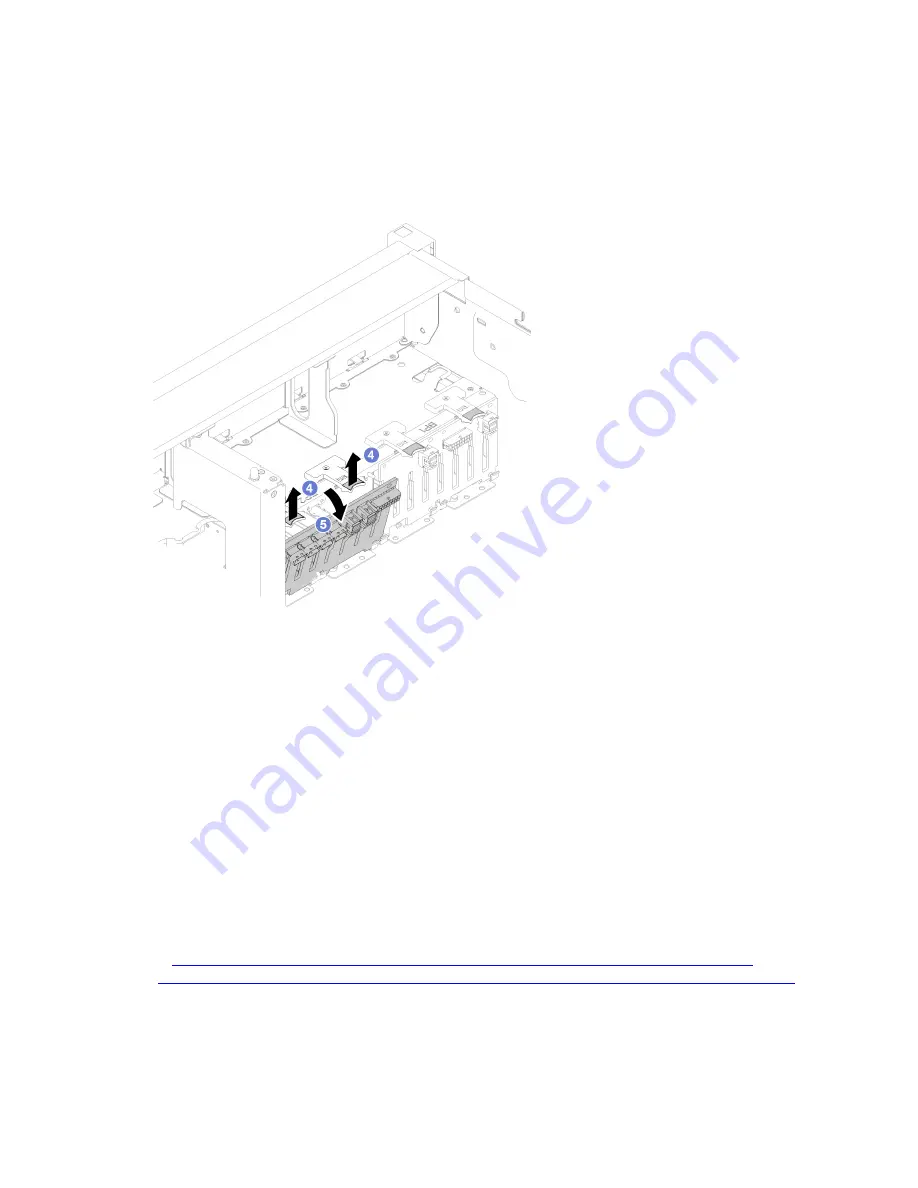
Step 4. Lift and hold the retention latches on top of the backplane.
Step 5. Rotate the backplane from the top toward the center of the server to disengage it from the retention
latches.
Figure 49. Drive backplane removal
If you are instructed to return the component or optional device, follow all packaging instructions, and use
any packaging materials for shipping that are supplied to you.
Install a drive backplane
Use this procedure to install a drive backplane.
Before installing a drive backplane:
1. Read the safety information and installation guidelines (see “Safety” on page iii and “Installation
2. Touch the static-protective package that contains the component to any unpainted metal surface on the
server; then, remove it from the package and place it on a static-protective surface.
To install a drive backplane, complete the following steps:
Watch the procedure
. A video of the process is available:
• Youtube:
https://www.youtube.com/watch?v=pIb0bIyfkDY&=PLYV5R7hVcs-Ak9fT8QAx8fLbEivizjRtp
• Youku:
http://v.youku.com/v_show/id_XMzMyODU3NTY2NA==.html?spm=a2hzp.8253876.0.0&f=51276390
Step 1. Align the tabs on the bottom of the drive backplane with the slots on the system board, and insert
them into the slots.
Step 2. Push the top of the drive backplane toward the front of the server until it clicks in place.
62
ThinkSystem SR860 Maintenance Manual
Summary of Contents for ThinkSystem SR860
Page 1: ...ThinkSystem SR860 Maintenance Manual Machine Type 7X69 7X70 ...
Page 8: ...vi ThinkSystem SR860 Maintenance Manual ...
Page 63: ...Figure 48 Server components Chapter 2 Server components 55 ...
Page 200: ...192 ThinkSystem SR860 Maintenance Manual ...
Page 210: ...202 ThinkSystem SR860 Maintenance Manual ...
Page 211: ......
Page 212: ...Part Number SP47A30805 Printed in China 1P P N SP47A30805 1PSP47A30805 ...


