
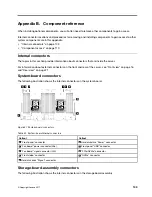

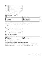


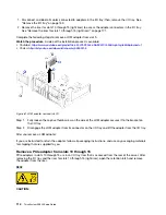

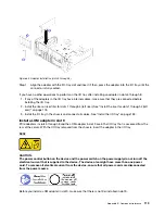
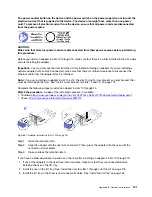


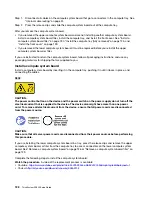
Figure 60. Adapter removal (slots 5 through 8)
Step 1. Disengage the adapter from its connector on the I/O tray and lift the adapter from the I/O tray.
After you remove the adapter:
If you are instructed to return the adapter, follow all packaging instructions, and use any packaging materials
for shipping that are supplied to you.
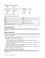
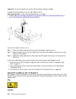
Remove a LOM adapter from slot 9
PCIe adapters in slots 5 through 8 and the LOM adapter in slot 9 are in the I/O tray that is accessed from the
rear of the server. After removing the I/O tray from the chassis and remove the adapter from the I/O tray.
S002
CAUTION:
The power control button on the device and the power switch on the power supply do not turn off the
electrical current that is supplied to the device. The device also might have more than one power
cord. To remove all electrical current from the device, ensure that all power cords are disconnected
from the power source.
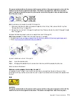
CAUTION:
Make sure that all server power cords are disconnected from their power sources before performing
this procedure.
Before you remove a LOM adapter from slot 9:
Appendix B. Component reference
113
Summary of Contents for ThinkSystem SR950 7X11
Page 1: ...ThinkSystem SR950 Setup Guide Machine Types 7X12 7X11 and 7X13 ...
Page 4: ...ii ThinkSystem SR950 Setup Guide ...
Page 18: ...14 ThinkSystem SR950 Setup Guide ...
Page 44: ...Figure 22 Server components 40 ThinkSystem SR950 Setup Guide ...
Page 48: ...44 ThinkSystem SR950 Setup Guide ...
Page 98: ...94 ThinkSystem SR950 Setup Guide ...
Page 106: ...102 ThinkSystem SR950 Setup Guide ...
Page 166: ...162 ThinkSystem SR950 Setup Guide ...
Page 199: ...X XCC management front USB configuration 87 Copyright Lenovo 2017 195 ...
Page 200: ...196 ThinkSystem SR950 Setup Guide ...
Page 201: ......
Page 202: ......


