

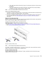
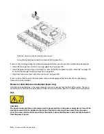
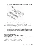

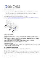

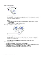


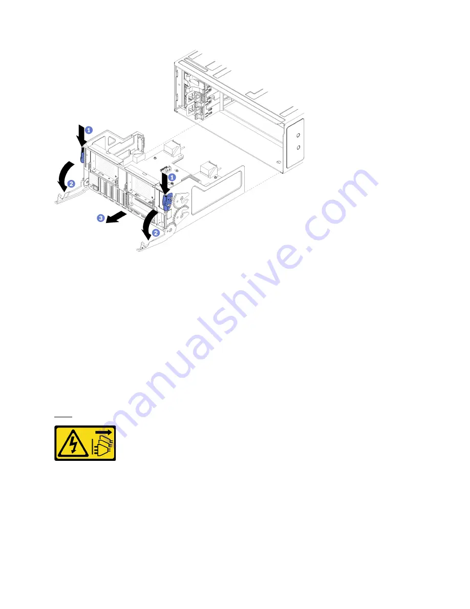
Figure 90. I/O tray removal
Step 1. Press the button on each release lever; then, simultaneously rotate the release levers until they are
perpendicular to the chassis.
Step 2. Pull I/O tray out of the chassis.
After you remove the I/O tray:
• If you are instructed to return the I/O tray, follow all packaging instructions, and use any packaging
materials for shipping that are supplied to you.
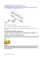
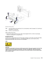
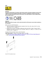
Install the I/O tray
Install the I/O tray by inserting it in the rear of the chassis, pushing it in until it stops, and closing the release
levers. If you are installing a new I/O tray as a maintenance replacement, you must transfer system
identification information as part of the new I/O tray installation.
S002
CAUTION:
The power control button on the device and the power switch on the power supply do not turn off the
electrical current that is supplied to the device. The device also might have more than one power
cord. To remove all electrical current from the device, ensure that all power cords are disconnected
from the power source.
Appendix B. Component reference
153
Summary of Contents for ThinkSystem SR950 7X11
Page 1: ...ThinkSystem SR950 Setup Guide Machine Types 7X12 7X11 and 7X13 ...
Page 4: ...ii ThinkSystem SR950 Setup Guide ...
Page 18: ...14 ThinkSystem SR950 Setup Guide ...
Page 44: ...Figure 22 Server components 40 ThinkSystem SR950 Setup Guide ...
Page 48: ...44 ThinkSystem SR950 Setup Guide ...
Page 98: ...94 ThinkSystem SR950 Setup Guide ...
Page 106: ...102 ThinkSystem SR950 Setup Guide ...
Page 166: ...162 ThinkSystem SR950 Setup Guide ...
Page 199: ...X XCC management front USB configuration 87 Copyright Lenovo 2017 195 ...
Page 200: ...196 ThinkSystem SR950 Setup Guide ...
Page 201: ......
Page 202: ......


