

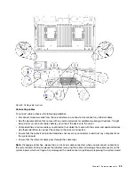
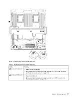
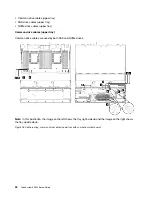

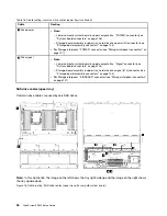
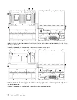


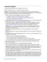

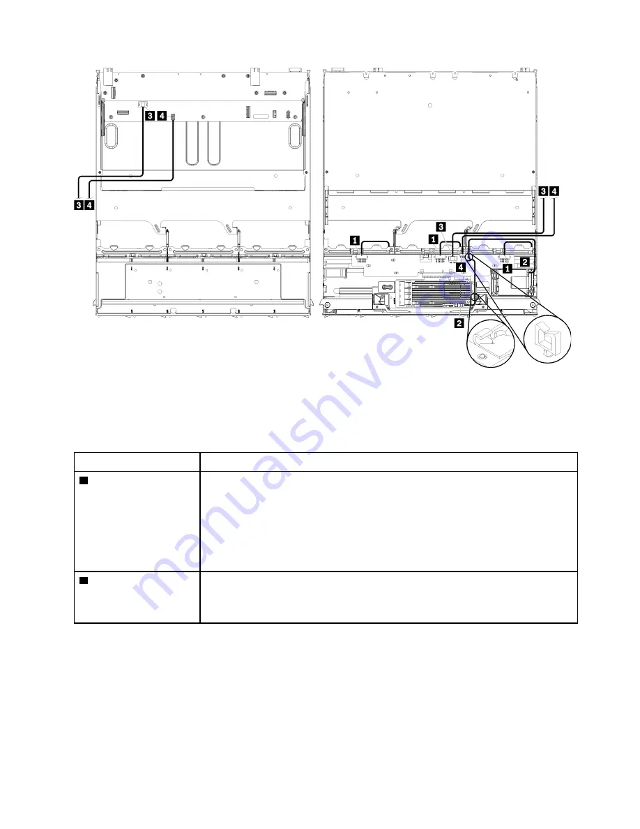
Note:
In this illustration, the image on the left shows the tray right-side up and the image on the right shows
the tray upside down.
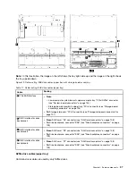
Figure 17. Cable routing, common drive cables (upper tray with storage-board assembly)
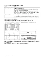
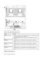
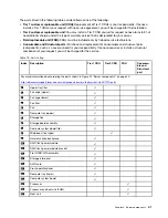
Table 16. Cable routing, common drive cables (upper tray)
Cable
Routing
1
Power to drive
backplanes 4, 5, and 6
•
From:
Storage interposer (see “Storage interposer connectors” on page 107)
– For drive backplane 4, use interposer “BP 3/4” connector
– For drive backplane 5, use interposer “BP 2/5” connector
– For drive backplane 6, use interposer “BP 1/6” connector
•
To:
Drive backplane, connector “Power” (see “Drive backplane connectors” on page
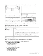
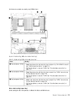
2
RAID flash power
module
•
From:
RAID flash power module connector
•
To:
RAID card, flash power module (J14) connector (see “RAID card connectors” on
.
35
Summary of Contents for ThinkSystem SR950 7X11
Page 1: ...ThinkSystem SR950 Setup Guide Machine Types 7X12 7X11 and 7X13 ...
Page 4: ...ii ThinkSystem SR950 Setup Guide ...
Page 18: ...14 ThinkSystem SR950 Setup Guide ...
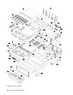
Page 44: ...Figure 22 Server components 40 ThinkSystem SR950 Setup Guide ...
Page 48: ...44 ThinkSystem SR950 Setup Guide ...
Page 98: ...94 ThinkSystem SR950 Setup Guide ...
Page 106: ...102 ThinkSystem SR950 Setup Guide ...
Page 166: ...162 ThinkSystem SR950 Setup Guide ...
Page 199: ...X XCC management front USB configuration 87 Copyright Lenovo 2017 195 ...
Page 200: ...196 ThinkSystem SR950 Setup Guide ...
Page 201: ......
Page 202: ......


