

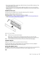


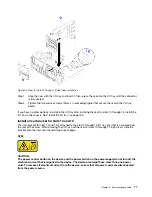


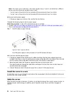


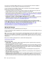


Figure 42. Riser for slots 10 through 15 (right riser) installation
Step 1. Align the riser with the I/O tray and insert it; then, press the riser into the I/O tray until the connector
is fully seated.
Step 2. Tighten the two captive screws (items 4 in preceding figure) that secure the riser to the I/O tray
board.
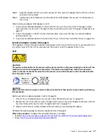
If you have no other options to install in the I/O tray after installing the riser for slots 10 through 15, install the
I/O tray in the chassis. See “Install the I/O tray” on page 153.
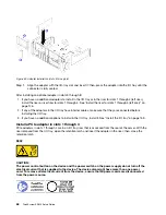
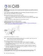
Install a riser bracket for slots 14 and 15
The riser bracket for slots 14 and 15 is attached to the slot 10 through 15 I/O tray riser that is accessed from
the rear of the server. After removing the I/O tray and the riser for slots 10 through 15 (right riser), slide the
bracket onto the riser until the retaining clips engage.
S002
CAUTION:
The power control button on the device and the power switch on the power supply do not turn off the
electrical current that is supplied to the device. The device also might have more than one power
cord. To remove all electrical current from the device, ensure that all power cords are disconnected
from the power source.
.
77
Summary of Contents for ThinkSystem SR950 7X11
Page 1: ...ThinkSystem SR950 Setup Guide Machine Types 7X12 7X11 and 7X13 ...
Page 4: ...ii ThinkSystem SR950 Setup Guide ...
Page 18: ...14 ThinkSystem SR950 Setup Guide ...
Page 44: ...Figure 22 Server components 40 ThinkSystem SR950 Setup Guide ...
Page 48: ...44 ThinkSystem SR950 Setup Guide ...
Page 98: ...94 ThinkSystem SR950 Setup Guide ...
Page 106: ...102 ThinkSystem SR950 Setup Guide ...
Page 166: ...162 ThinkSystem SR950 Setup Guide ...
Page 199: ...X XCC management front USB configuration 87 Copyright Lenovo 2017 195 ...
Page 200: ...196 ThinkSystem SR950 Setup Guide ...
Page 201: ......
Page 202: ......


