background image

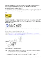
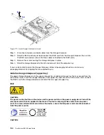
After you remove the storage tray:

•  If you are instructed to return the storage tray, follow all packaging instructions, and use any packaging 

materials for shipping that are supplied to you.

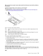
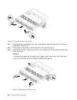
Install the storage tray (fully removed)

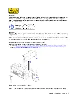
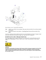
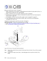
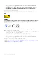
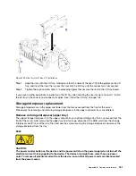
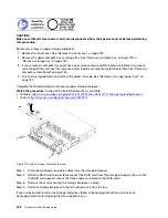
Install the storage tray when it is fully removed by inserting it in the front of the chassis, pushing it in until it 
stops, and closing the release levers.

S002  

CAUTION: 
The power control button on the device and the power switch on the power supply do not turn off the 
electrical current that is supplied to the device. The device also might have more than one power 
cord. To remove all electrical current from the device, ensure that all power cords are disconnected 
from the power source.

Before you install an optional storage tray:

1.  Make sure that all cables, adapters, and other components are installed and seated correctly and that 

you have not left loose tools or parts inside the server. 

2.  Make sure that all internal cables are correctly routed. See “Internal cable routing” on page 24.

Complete the following steps to install a storage tray when it is fully removed from the chassis:

Watch the procedure

. A video of the replacement process is available: 

•  Youtube: 

https://www.youtube.com/playlist?list=PLYV5R7hVcs-DbSYJFY74PoKmph7vgrkKH&playnext=1

•  Youku: 

http://list.youku.com/albumlist/show/id_50952215

Appendix B. Component reference

189

Summary of Contents for ThinkSystem SR950 7X11

Page 1: ...ThinkSystem SR950 Setup Guide Machine Types 7X12 7X11 and 7X13 ...

Page 2: ...s where children are likely to be present In addition be sure that you are familiar with the terms and conditions of the Lenovo warranty for your server which can be found at http datacentersupport lenovo com warrantylookup Second Edition December 2017 Copyright Lenovo 2017 LIMITED AND RESTRICTED RIGHTS NOTICE If data or software is delivered pursuant to a General Services Administration GSA contr...

Page 3: ... 87 Set front USB port for Lenovo XClarity Controller connection 87 Update the firmware 88 Configure the firmware 91 Memory configuration 91 Independent memory mode 92 Memory mirroring 92 Memory sparing 92 RAID configuration 92 Install the operating system 93 Back up the server configuration 93 Chapter 5 Resolving installation issues 95 Appendix A Getting help and technical assistance 99 Before yo...

Page 4: ...ii ThinkSystem SR950 Setup Guide ...

Page 5: ...k using these rails are in the Rack Installation Instructions document packaged with your server Material box including items such as the power cords printed documentation and an accessory kit If any item is missing or damaged contact your place of purchase Ensure that you retain your proof of purchase and packing material They might be required to receive warranty service Features Performance eas...

Page 6: ...rt or 4 port or 2x 10Gb SFP 2 port or 4 port An ML2 form factor network adapter is also supported Integrated Trusted Platform Module TPM This integrated security chip performs cryptographic functions and stores private and public secure keys It provides the hardware support for the Trusted Computing Group TCG specification You can download the software to support the TCG specification when the sof...

Page 7: ...ot mix power supply types in the server ThinkSystem RAID support The ThinkSystem RAID adapter provides hardware redundant array of independent disks RAID support to create configurations The standard RAID adapter provides RAID levels 0 and 1 An optional RAID adapter is available for purchase Specifications The following information is a summary of the features and specifications of the server Depe...

Page 8: ...ttings Single rank or dual rank Registered DIMM RDIMM load reduced DIMM LRDIMM or three dimensional stacking registered DIMM 3DS RDIMM Slots 24 dual inline in each compute tray 96 DIMMs maximum Supports depending on the model 16 GB 32 GB RDIMMs 64 GB LRDIMMs 128 GB 3DS RDIMMs Drive expansion Up to six SAS SATA NVMe drive backplanes Up to 24 2 5 inch hot swap drive bays Up to 24 SATA SAS drives dep...

Page 9: ...0 x16 low profile Slot 6 PCI Express 3 0 x16 low profile Slot 7 PCI Express 3 0 x8 low profile Slot 8 ML2 x16 network adapter with NC SI support Slot 9 LOM adapter Slot 10 15 PCI Express 3 0 for PCIe riser card with the following slots available depending on the riser card installed 1 x8 x8 x8 x8 PCIe full height riser kit provides Slot 10 PCI Express 3 0 x8 Slot 11 PCI Express 3 0 x8 Slot 12 PCI ...

Page 10: ...10 5 cacheless ThinkSystem 430 16i Basic Hardware RAID PCIe Adapter supports RAID levels 0 1 10 5 cacheless ThinkSystem 530 8i Basic Hardware RAID PCIe Adapter RAID levels 0 1 10 5 cacheless ThinkSystem 730 8i Value Advanced Hardware RAID 1 GB Cache PCIe Adapter supports RAID levels 0 1 5 10 ThinkSystem RAID 930 8i Advanced Hardware 2 GB Flash Cache PCIe Adapter supports RAID levels 0 1 5 6 10 50 ...

Page 11: ...3050 m 10 006 ft derate maximum dry bulb temperature 1 C 33 F per 125 m 410 ft above 950 m 3 117 ft Maximum rate of change 20 C 68 F per hour Server off 5 to 45 C 41 to 113 F Shipment 40 C to 60 C 40 F to 140 F Humidity range noncondensing Server on Minimum higher more moisture of 12 C 10 F dew point and 8 to 90 relative humidity maximum dew point 24 C 75 F Server off 8 to 90 relative humidity max...

Page 12: ...ity Essentials OneCLI Lenovo XClarity Essentials Bootable Media Creator and Lenovo XClarity Essentials UpdateXpress 2 Most options can be updated through the Lenovo tools Some options such as GPU firmware or Omni Path firmware require the use of vendor tools 3 Firmware updates are limited to Lenovo XClarity Provisioning Manager Lenovo XClarity Controller firmware and UEFI updates only Firmware upd...

Page 13: ...at you manage Operating System deployment You can use Lenovo XClarity Administrator to manage a repository of operating system images and to deploy operating system images to up to 28 managed servers concurrently Service and support Lenovo XClarity Administrator can be set up to collect and send diagnostic files automatically to your preferred service provider when certain serviceable events occur...

Page 14: ... during emergency power event such as a data center power failure For more information about downloading installation and usage see https datacentersupport lenovo com solutions lnvo lxem Lenovo XClarity Provisioning Manager Lenovo XClarity Provisioning Manager is embedded software that provides a graphic user interface GUI for configuring the system with support for 10 languages It simplifies the ...

Page 15: ...ver management utilities that provides a less complicated method to enable customers to manage Lenovo ThinkSystem System x and Thinkserver servers more efficiently and cost effectively Lenovo XClarity Essentials includes the following utilities Lenovo XClarity Essentials OneCLI is a collection of several command line applications which can be used to Configure the server Collect service data for t...

Page 16: ...cessor Whenever power is applied to a server the management processor is available From the management processor interface you can perform the following functions Monitor all hardware devices installed in the server Power the server on and off View the system event log and system audit log for the server Use the Remote management function to log in to the server itself Documentation for Lenovo XCl...

Page 17: ... to keep user data safe and to erase confidential data completely from a hard disk drive Lenovo Business Vantage provides the following functions Data Safe Encrypt files to ensure data safety by using the TCM adapter Sure Erase Erase confidential data from a hard disk This tool follows the industry standard method to do the erasing and allows the user to select different erasing levels Smart USB P...

Page 18: ...14 ThinkSystem SR950 Setup Guide ...

Page 19: ... the customer label spaces 1 in the following illustration Note If any customer labels are placed on the removable front cover make sure that the cover remains installed on the same server where the labels were originally added Figure 1 Location of the ID label for the Lenovo ThinkSystem SR950 QR code In addition the service label that is located at the top rear of the compute system board inside ...

Page 20: ... server and must be removed before operating the system The label provides the default IPv4 host name and default IPv6 link local address of the XCC Figure 3 Network access tag Front view The front view of the server varies slightly by the model In some models components are replaced by fillers 16 ThinkSystem SR950 Setup Guide ...

Page 21: ... the server Callout Callout 1 2 5 inch drive bays 12 23 some models 7 Power button and power LED see Front operator panel on page 18 2 Fans 1 12 8 Front operator panel with pull out LCD display see LCD system information display panel on page 19 3 2 5 inch drive bays 0 11 9 USB 2 0 port 4 System error LED see Front operator panel on page 18 10 USB 2 0 Lenovo XClarity Controller management port see...

Page 22: ...flashes per second it indicates that the controller is identifying the drive Front operator panel The following illustration shows the controls and LEDs on the front operator panel Table 4 Operator panel front controls and indicators Callout Callout 1 Power button and power LED 3 System ID button LED 2 Network activity LED 4 System error LED 1 Power button and power LED Press this button to turn t...

Page 23: ...comes with a tab which can be pulled to access the LCD system information display panel See LCD system information display panel on page 19 for more information LCD system information display panel The following section includes an overview of the LCD system information display panel which displays various types of information about the server The LCD system information display panel attached to t...

Page 24: ...he following is an illustration of the LCD system information display panel menu options flow Following is an example of the information on the display panel Table 6 LCD system information display information Callout Callout 1 System name 4 UEFI POST code 2 Ambient temperature 5 System status 3 Estimated power consumption Following is an illustration of the LCD system information display panel men...

Page 25: ...e server Lenovo XClarity Controller LXCC system error log Note The Scroll Down button will only function for this menu option when errors occur A list of current errors reported by the system will be displayed System VPD information Machine type and serial number Universal Unique Identifier UUID string System firmware levels UEFI code level LXCC code level LXCC network information LXCC hostname LX...

Page 26: ...riser card 2 23 XClarity Controller network connector RJ45 11 PCIe slot 11 on riser card 2 24 Serial connector 12 PCIe slot 12 on riser card 2 25 USB 3 0 connectors 2 13 PCIe slot 13 on riser card 2 26 VGA video port Notes The following PCIe slots are assigned to components elsewhere in the server PCIe slot 18 is assigned to the RAID card in the lower tray PCIe slot 19 is assigned to the RAID card...

Page 27: ...e output does not meet the power supply input requirements for example a 1600 watt power supply will not run off of 120 vac input On The power supply is receiving the correct input power and the power supply is operating normally 2 Output status DC green The output status LED can be in one of the following states Off The server is powered off not connected to input power the power supply is not wo...

Page 28: ...15 fault LED 5 Adapter 1 fault LED 16 Adapter 16 fault LED 6 Adapter 2 fault LED 17 Adapter 17 fault LED 7 Adapter 3 fault LED 18 Riser 16 through 17 fault LED 8 Adapter 4 fault LED 22 3v fault system battery LED 9 Riser 10 through 15 fault LED 23 I O board fault LED 10 Adapter 10 fault LED 24 LOM adapter fault LED 11 Adapter 11 fault LED 25 ML2 x16 network adapter fault LED 12 Adapter 12 fault LE...

Page 29: ...s that come with the server and optional devices Use these identifiers to connect the cables to the correct connectors Ensure that the cable is not pinched and does not cover any connectors or obstruct any components on the system board Ensure that the relevant cables pass through the cable clips Note Disengage all latches release tabs or locks on cable connectors when you disconnect cables from t...

Page 30: ... cable routing upper tray on page 28 Notes Make sure that all the cables go through the cable guides as shown in the illustrations See Cable guides on page 24 for cable guide locations and descriptions Some cable connectors have locks or latches that must be disengaged to disconnect the cable Common cable routing lower tray The following illustration shows cable routing for common components in th...

Page 31: ...o port From Front panel video port To Lower compute system board in lower compute tray Front video connector see System board connectors on page 103 2 Front panel USB ports From Front USB ports To Lower compute system board in lower compute tray USB connector see System board connectors on page 103 Chapter 2 Server components 27 ...

Page 32: ...om pinching when the compute tray is fully assembled 4 Fan cage cable From Fan cage connector underside of fan cage To Lower compute system board in lower compute tray Fan board power J56 and signal J40 connectors see System board connectors on page 103 Common cable routing upper tray The following illustration shows cable routing for common components in the upper tray Note In this illustration t...

Page 33: ...ge board assembly in upper tray fan power J3 and signal J5 connectors see Storage board assembly connectors on page 103 Note Do not route the fan cage cable in the upper tray through any cable guides Cable routing for drives Use this section to understand how to route cables for drives and related components Cable routing for drive components is different for the lower and upper trays Drive cable ...

Page 34: ...at must be disengaged to disconnect the cable Drive cable routing lower tray Cable routing for drive components is different for SAS and NVMe drives Common drive cables lower tray SAS drive cables lower tray NVMe drive cables lower tray Common drive cables lower tray Common drive cables are used by both SAS and NVMe drives Figure 13 Cable routing common drive cables lower tray 30 ThinkSystem SR950...

Page 35: ...m RAID flash power module connector To RAID card flash power module J14 connector see RAID card connectors on page 108 3 Drive power From Lower compute system board in lower compute tray POWER connector see System board connectors on page 103 To Storage interposer POWER connector see Storage interposer connectors on page 107 4 Drive signal From Lower compute system board in lower compute tray Sign...

Page 36: ...lane 1 From RAID card C3 connector see RAID card connectors on page 108 To Drive backplane connector SAS see Drive backplane connectors on page 109 3 RAID interface for drive backplane 2 From RAID card C2 connector see RAID card connectors on page 108 To Drive backplane connector SAS see Drive backplane connectors on page 109 4 RAID interface for drive backplane 3 From RAID card C1 connector see R...

Page 37: ...s on page 109 2 Drive backplane 2 NVMe From Upper compute system board in lower compute tray NVMe connector see System board connectors on page 103 To Drive backplane 2 connector NVMe see Drive backplane connectors on page 109 3 Drive backplane 3 NVMe From Lower compute system board in lower compute tray NVMe connector see System board connectors on page 103 To Drive backplane 3 connector NVMe see...

Page 38: ...pper tray Common drive cables are used by both SAS and NVMe drives Note In this illustration the image on the left shows the tray right side up and the image on the right shows the tray upside down Figure 16 Cable routing common drive cables upper tray with compute system board 34 ThinkSystem SR950 Setup Guide ...

Page 39: ...planes 4 5 and 6 From Storage interposer see Storage interposer connectors on page 107 For drive backplane 4 use interposer BP 3 4 connector For drive backplane 5 use interposer BP 2 5 connector For drive backplane 6 use interposer BP 1 6 connector To Drive backplane connector Power see Drive backplane connectors on page 109 2 RAID flash power module From RAID flash power module connector To RAID ...

Page 40: ...wer compute system board in upper compute tray Signal connector see System board connectors on page 103 Storage board assembly in upper tray hard disk drive signal J13 connector see Storage board assembly connectors on page 103 To Storage interposer SIDEBAND connector see Storage interposer connectors on page 107 SAS drive cables upper tray Common drive cables are used by only SAS drives Note In t...

Page 41: ...ge interposer PCIe connector see Storage interposer connectors on page 107 2 RAID interface for drive backplane 4 From RAID card C3 connector see RAID card connectors on page 108 To Drive backplane connector SAS see Drive backplane connectors on page 109 3 RAID interface for drive backplane 5 From RAID card C2 connector see RAID card connectors on page 108 To Drive backplane connector SAS see Driv...

Page 42: ...down Figure 20 Cable routing NVMe drive cables upper tray with compute system board Note In this illustration the image on the left shows the tray right side up and the image on the right shows the tray upside down Figure 21 Cable routing NVMe drive cables upper tray with storage board assembly 38 ThinkSystem SR950 Setup Guide ...

Page 43: ...s on page 103 To Drive backplane 5 connector NVMe see Drive backplane connectors on page 109 3 Drive backplane 4 NVMe From Upper compute system board in upper compute tray NVMe connector see System board connectors on page 103 Storage board assembly in upper tray NVMe connector see Storage board assembly connectors on page 103 To Drive backplane 4 connector NVMe see Drive backplane connectors on p...

Page 44: ...Figure 22 Server components 40 ThinkSystem SR950 Setup Guide ...

Page 45: ...ur responsibility If Lenovo acquires or installs a structural component at your request you will be charged for the service Table 19 Parts listing Index Description Tier 1 CRU Tier 2 CRU FRU Consuma ble and Structural part For more information about ordering the parts shown in Figure 22 Server components on page 40 http datacentersupport lenovo com us en products servers thinksystem sr950 7X12 par...

Page 46: ...17 27 PCIe filler four slot 28 Riser bracket slots 14 and 15 28 PCIe filler two slot 28 Riser bracket filler slots 14 and 15 29 PCIe filler single slot 30 Riser slots 1 through 4 or 10 through 13 31 Bezel front 32 Cover front 33 Hard disk drive 34 Hard disk drive filler single bay or four bay 35 Chassis 36 Cable covers 37 M 2 backplane 38 M 2 drive 39 I O tray 40 Adapter LOM or ML2 x16 network 41 ...

Page 47: ...anadian Standards Association CSA For units intended to be operated at 115 volts Use a UL listed and CSA certified cord set consisting of a minimum 18 AWG Type SVT or SJT three conductor cord a maximum of 15 feet in length and a parallel blade grounding type attachment plug rated 15 amperes 125 volts For units intended to be operated at 230 volts U S use Use a UL listed and CSA certified cord set ...

Page 48: ...44 ThinkSystem SR950 Setup Guide ...

Page 49: ... to the server See Rear view on page 21 to locate the connectors See Cable the server on page 84 for cabling best practices d Power on the server See Power on the server connect input power on page 85 Note You can access the management processor interface to configure the system without powering on the server Whenever the server is connected to power the management processor interface is available...

Page 50: ...s not shake or tilt Do not attempt to lift an object that might be too heavy for you If you have to lift a heavy object read the following precautions carefully Make sure that you can stand steadily without slipping Distribute the weight of the object equally between your feet Use a slow lifting force Never move suddenly or twist when you lift a heavy object To avoid straining the muscles in your ...

Page 51: ...oved hot swap power supply must be replaced within two minutes after removal Every air baffle that comes with the server must be installed when the server starts some servers might come with more than one air baffle Operating the server with a missing air baffle might damage the processor All processor sockets must contain either a socket cover or a processor with heat sink When more than one proc...

Page 52: ...en Always download and apply the latest firmware This will help ensure that any known issues are addressed and that your server is ready to work with optimal performance Go to Lenovo ThinkSystem SR950 Drivers and Software to download firmware updates for your server It is good practice to make sure that the server is working correctly before you install an optional component Follow the installatio...

Page 53: ...ght have more than one power cord To remove all electrical current from the device ensure that all power cords are disconnected from the power source CAUTION Make sure that all server power cords are disconnected from their power sources before performing this procedure Notes If you are installing an optional processor or memory module perform those tasks first See Install a processor heat sink mo...

Page 54: ...ure that the rails on the board fit into the slots in the compute tray Step 2 Slide the compute system board into the compute tray until the release clips snap into the locked position Step 3 Connect all cables on the compute system board that go to connectors in the compute tray See Internal cable routing on page 24 After you install the compute system board If you installed the lower compute sys...

Page 55: ...ket contacts are very fragile and easily damaged Contaminants on the processor contacts such as oil from your skin can cause connection failures Remove and install only one PHM at a time If the system board supports multiple processors install the PHMs starting with the first processor socket Do not allow the thermal grease on the processor or heat sink to come in contact with anything Contact wit...

Page 56: ...ompute tray on page 123 3 If you are installing a PHM in the lower compute system board remove the upper compute system board or compute system board filler See Remove a compute system board on page 126 Figure 25 Processor locations on system board Figure 26 Processor layout for multi processor systems viewed from front of server Complete the following steps to install a PHM Watch the procedure A ...

Page 57: ...visually inspect to make sure that there is no gap between the screw shoulder beneath the heat sink and the processor socket For reference the torque required for the nuts to fully tighten is 1 4 1 6 newton meters 12 14 inch pounds After installing the PHM option 1 If there are memory modules to install install them See Install a memory module on page 54 Also install memory module fillers that are...

Page 58: ...quired installation order based on the number of processors and memory modules in your system and the memory mode that you are implementing See http www lenovo com us en serverproven for a list of all the memory module types and capacities that are supported for your server Notes Do not mix RDIMMs and LR DIMMs in the same server Install higher capacity ranked DIMMs first following the population s...

Page 59: ...rd 3 lower board upper tray DIMM number Compute system board 4 upper board upper tray DIMM number 1 1 25 49 73 2 2 26 50 74 3 3 27 51 75 4 4 28 52 76 5 5 29 53 77 6 6 30 54 78 7 7 31 55 79 8 8 32 56 80 9 9 33 57 81 10 10 34 58 82 11 11 35 59 83 12 12 36 60 84 13 13 37 61 85 14 14 38 62 86 15 15 39 63 87 16 16 40 64 88 17 17 41 65 89 18 18 42 66 90 19 19 43 67 91 20 20 44 68 92 21 21 45 69 93 22 22...

Page 60: ...ku http list youku com albumlist show id_50952215 Attention Memory modules are sensitive to static discharge and require special handling In addition to the standard guidelines for Handling static sensitive devices Always wear an electrostatic discharge strap when removing or installing memory modules Electrostatic discharge gloves can also be used Never hold two or more memory modules together so...

Page 61: ...e system board on page 128 2 Install the compute tray See Install the compute tray fully removed on page 125 3 If you have no additional options to install in the upper or lower compute tray install the front cover See Install the front cover on page 65 Install a hard disk drive backplane Hard disk drive backplanes are in the upper and lower compute trays that are accessed from the front of the se...

Page 62: ...es should be populated from right to left when viewed from the front of the server backplane for drives 20 23 first then 16 19 and 12 15 These population orders allow a mix of drive backplane types to be installed in the server 3 Apply new drive bay labels based on the backplane locations determined in the previous step Several drive bay labels come with each type of the supported drive backplane ...

Page 63: ...pper installation Align the backplane with its location in the tray then insert the backplane and push it down until it is fully seated Step 3 Connect the data cables to the backplane SAS backplanes have only one data cable NVME backplanes have two data cables See Cable routing for drives on page 29 Step 4 Repeat Step 1 on page 148 Step 2 on page 148 and Step 3 on page 149 for each hard disk drive...

Page 64: ...ted from the power source CAUTION Make sure that all server power cords are disconnected from their power sources before performing this procedure Note If you are installing a compute system board processor memory module as options in the lower compute tray perform these tasks first See Install the compute system board on page 49 Install a processor heat sink module on page 51 or Install a memory ...

Page 65: ...able or the compute system board NVMe cable See Cable routing for drives on page 29 Complete the following steps to install a hard disk drive backplane in the lower compute tray Watch the procedure A video of the replacement process is available Youtube https www youtube com playlist list PLYV5R7hVcs DbSYJFY74PoKmph7vgrkKH playnext 1 Youku http list youku com albumlist show id_50952215 Step 1 Conn...

Page 66: ...backplane 1 Install the storage interposer and connect all cables See Install a storage interposer lower tray on page 185 2 Make sure that all of the cables are correctly routed after they have been connected 3 Install the fan cage See Install a fan cage lower tray on page 137 4 If you have no additional options to install in the lower compute tray install it See Install the compute tray fully rem...

Page 67: ...plete the following steps to install a hard disk drive Watch the procedure A video of the installation process is available Youtube https www youtube com playlist list PLYV5R7hVcs DbSYJFY74PoKmph7vgrkKH playnext 1 Youku http list youku com albumlist show id_50952215 Note NVMe drive bays can accept either SATA SAS or NVMe drives Step 1 Determine the drive type that you can install in the bay SATA S...

Page 68: ...ives in its place place single bay fillers in any vacant bays Hard disk drive installation considerations Hard disk drives must be installed in a specific order based on the hard disk drive configuration that you implement on your server The following notes describe the type of hard disk drives that the server supports and other information that you must consider when installing a hard disk drive ...

Page 69: ...st show id_50952215 Figure 33 Front cover installation Step 1 Position the cover on the front of the server Note Make sure that the pull tab on the operator panel used to access the LCD system information display panel panel passes through the hole for the display panel on the front cover Step 2 Press and slide the cover toward the rear of the server until the release clips engage Install an adapt...

Page 70: ...lled in the server remove it See Remove the I O tray on page 152 2 Remove the riser for slots 10 through 15 right riser to access the adapter connectors in the I O tray See Remove the riser for slots 10 through 15 right riser on page 171 3 Make sure that there is no filler installed in slot 9 Complete the following steps to install a LOM adapter in slot 9 Watch the procedure A video of the install...

Page 71: ... I O tray S002 CAUTION The power control button on the device and the power switch on the power supply do not turn off the electrical current that is supplied to the device The device also might have more than one power cord To remove all electrical current from the device ensure that all power cords are disconnected from the power source CAUTION Make sure that all server power cords are disconnec...

Page 72: ...re installing the I O tray 3 If you have no additional options to install in the I O tray install it See Install the I O tray on page 153 Install a PCIe adapter in slots 1 through 4 PCIe adapters in slots 1 through 4 are in an I O tray riser that is accessed from the rear of the server With the riser removed from the I O tray open the retention latch and insert the adapter in the riser then close ...

Page 73: ...hVcs DbSYJFY74PoKmph7vgrkKH playnext 1 Youku http list youku com albumlist show id_50952215 Figure 36 Adapter installation slots 1 through 4 Step 1 Open the retention latch Step 2 Align the adapter with the riser slot and insert it then press the adapter into the riser until the connector is fully seated Step 3 Close and lock the retention latch If you have no additional adapters to install in the...

Page 74: ...onnector make sure that there is sufficient clearance to disconnect the Ethernet cable from the adapter after it is installed 2 Remove the riser for slots 10 through 15 right riser See Remove the riser for slots 10 through 15 right riser on page 171 3 Make sure that there is no filler installed in the slot where you are installing the adapter Note If you are installing an adapter in slot 14 or 15 ...

Page 75: ...lso might have more than one power cord To remove all electrical current from the device ensure that all power cords are disconnected from the power source Attention The adapter installed in slot 16 must have a metal bezel with holes no larger than 3 0 mm in any dimension CAUTION Make sure that all server power cords are disconnected from their power sources before performing this procedure Before...

Page 76: ...stalling the riser in the I O tray 2 Install the riser in the I O tray See Install the riser for slots 16 and 17 on page 180 3 If you have no additional options to install in the I O tray install it See Install the I O tray on page 153 Install an M 2 drive Use this information to install an M 2 drive option S002 CAUTION The power control button on the device and the power switch on the power suppl...

Page 77: ...list list PLYV5R7hVcs DbSYJFY74PoKmph7vgrkKH playnext 1 Youku http list youku com albumlist show id_50952215 Step 1 Locate the connector on each side of the M 2 backplane Step 2 Insert the M 2 drive Figure 39 Inserting the M 2 drives Insert the M 2 drive at an angle approximately 30 degrees into the connector and rotate it until the notch catches on the lip of the retainer Notes When installing tw...

Page 78: ...r information Install a riser Risers are in the I O tray that is accessed from the rear of the server Install adapters before installing the risers Install the riser for slots 1 through 4 left riser The riser for adapter slots 1 through 4 left riser is in the I O tray that is accessed from the rear of the server After installing adapters in the riser insert the riser in the I O tray and secure it ...

Page 79: ...ure that they are connected before installing the riser in the I O tray Complete the following steps to install the riser for slots 1 through 4 Watch the procedure A video of the installation process is available Youtube https www youtube com playlist list PLYV5R7hVcs DbSYJFY74PoKmph7vgrkKH playnext 1 Youku http list youku com albumlist show id_50952215 Figure 41 Riser for slots 1 through 4 left r...

Page 80: ... for slots 10 through 15 right riser See Install a LOM adapter in slot 9 on page 65 Before you install the riser for slots 10 through 15 option 1 If the I O tray is installed in the server remove it See Remove the I O tray on page 152 2 Make sure that there is no screw item 2 in following figure securing the I O tray board to the I O tray in a location where a captive riser screw will be installed...

Page 81: ...nstall a riser bracket for slots 14 and 15 The riser bracket for slots 14 and 15 is attached to the slot 10 through 15 I O tray riser that is accessed from the rear of the server After removing the I O tray and the riser for slots 10 through 15 right riser slide the bracket onto the riser until the retaining clips engage S002 CAUTION The power control button on the device and the power switch on t...

Page 82: ...uku com albumlist show id_50952215 Figure 43 Riser bracket installation slots 14 and 15 Step 1 Align the slots on the riser bracket with the pins on the riser and slide it in place then press the bracket onto the riser until the retaining clips engage After installing the optional riser bracket for slots 14 and 15 1 Install adapters in the riser See Install a PCIe adapter in slots 10 through 15 on...

Page 83: ...d 17 1 If the I O tray is installed in the server remove it See Remove the I O tray on page 152 2 Make sure that there is no screw item 2 in following figure securing the I O tray board to the I O tray in a location where a captive riser screw will be installed 3 Make sure that there are no I O tray fillers installed in adapter slots 16 and 17 4 Install adapters in the riser See Install an I O ada...

Page 84: ...s 16 and 17 install the I O tray in the chassis See Install the I O tray on page 153 Install the M 2 backplane The M 2 backplane is in the I O tray that is accessed from the rear of the server After installing M 2 drives in the backplane insert the backplane in the I O tray and press it in place S002 CAUTION The power control button on the device and the power switch on the power supply do not tur...

Page 85: ...be com playlist list PLYV5R7hVcs DbSYJFY74PoKmph7vgrkKH playnext 1 Youku http list youku com albumlist show id_50952215 Figure 45 M 2 backplane installation Step 1 Align the openings in the plastic supports at each end of the M 2 backplane with the guide pins on the system board then insert the backplane in the system board connector Step 2 Press down on the M 2 backplane to fully seat it After in...

Page 86: ...es Connect and disconnect cables as described in the following table when installing moving or opening covers on this product or attached devices To Connect To Disconnect 1 Turn everything OFF 2 First attach all cables to devices 3 Attach signal cables to connectors 4 Attach power cords to outlet 5 Turn device ON 1 Turn everything OFF 2 First remove power cords from outlet 3 Remove signal cables f...

Page 87: ...depending on how many processors are installed the number of power supplies that are required to keep the system operating which power supply bays are populated and the number of input power sources as shown in the following table Table 21 Power supply redundancy Total number of processors installed in server Minimum number of power supplies to maintain system operation Bays where power supplies a...

Page 88: ... you have installed a power supply 1 If the power supplies being installed are of a different wattage than the power supplies previously installed in the chassis cover the existing chassis power rating label with a new label of the same style from the system power rating labels sheet that comes with the power supply option 2 Route the power cable from the power supply to the power source and secur...

Page 89: ...urce Turn on the server The server can be turned on power LED on in any of the following ways You can press the power button The server can start or restart automatically after a power interruption The server can respond to remote power on requests sent to the Lenovo XClarity Controller For information about powering off the server see Power off the server disconnect input power on page 85 Validat...

Page 90: ...te The Lenovo XClarity Controller can place the server in a standby state as an automatic response to a critical system failure Start an orderly shutdown using the operating system if supported by your operating system Press the power button to start an orderly shutdown if supported by your operating system Press and hold the power button for more than 4 seconds to force a shutdown When in a stand...

Page 91: ...e Lenovo XClarity Controller is set initially with a user name of USERID and password of PASSW0RD with a zero not the letter O This default user setting has Supervisor access Change this user name and password during your initial configuration for enhanced security You can use the Lenovo XClarity Administrator Mobile app to connect to the Lenovo XClarity Controller interface and configure the netw...

Page 92: ...ptions html Update the firmware Several options are available to update the firmware for the server You can use the tools listed here to update the most current firmware for your server and the devices that are installed in the server Note Lenovo typically releases firmware in bundles called UpdateXpress System Packs UXSPs To ensure that all of the firmware updates are compatible you should update...

Page 93: ...on firmware updates Lenovo XClarity Essentials OneCLI Supports all core system firmware I O firmware and installed operating system driver updates Lenovo XClarity Essentials UpdateXpress Supports all core system firmware I O firmware and installed operating system driver updates Lenovo XClarity Essentials Bootable Media Creator Supports core system firmware and I O firmware updates You can update ...

Page 94: ... at http sysmgt lenovofiles com help topic com lenovo systems management xcc doc NN1ia_c_ manageserverfirmware html Lenovo XClarity Essentials OneCLI Lenovo XClarity Essentials OneCLI is a collection of command line applications that can be used to manage Lenovo servers Its update application can be used to update firmware and device drivers for your servers The update can be performed within the ...

Page 95: ...XClarity Controller and UEFI The saved configuration information can be used to replicate or restore other systems For information about configuring the server using Lenovo XClarity Essentials OneCLI see http sysmgt lenovofiles com help topic toolsctr_cli_lenovo onecli_c_settings_info_commands html Lenovo XClarity Administrator You can quickly provision and pre provision all of your servers using ...

Page 96: ...s surpassed in a system protected by memory sparing the content of a failing rank of DIMMs is copied to the spare rank The failing rank is then taken offline and the spare rank placed online for use as active memory in place of the failed rank Since the failover process involves copying of memory content the level of memory redundancy provided by memory sparing is less than that provided by memory...

Page 97: ...ty Provisioning Manager you can install the operating system manually For more information about installing a specific operating system 1 Go to http datacentersupport lenovo com and navigate to the support page for your server 2 Click How tos Solutions 3 Select an operating system and the installation instructions will be displayed Back up the server configuration After setting up the server or ma...

Page 98: ...94 ThinkSystem SR950 Setup Guide ...

Page 99: ...ications 4 Check the event log for any events related to the server not powering on 5 Check for any LEDs that are flashing amber 6 Disconnect and reconnect the input power cords 7 Make sure that the power cords are connected to a working electrical outlet that is providing the necessary levels of input power see the power supply labels for input power requirements 8 Reseat the power supplies 9 Rep...

Page 100: ...pervisor device is supported for the server 4 Make sure that the embedded hypervisor device is listed in the list of available boot options From the management controller user interface click Server Configuration Boot Options For information about accessing the management controller user interface see the XClarity Controller product documentation http sysmgt lenovofiles com help topic com lenovo s...

Page 101: ...t but the drives are not recognized replace the backplane signal cable and run the tests again Replace the backplane If the adapter fails the test disconnect the backplane signal cable from the adapter and run the tests again If the adapter fails the test replace the adapter Displayed system memory less than installed physical memory Complete the following steps until the problem is resolved 1 Mak...

Page 102: ...ce Whenever memory or any other device is changed you must update the configuration Make sure that the latest levels of device firmware and device drivers are installed See Update the firmware on page 88 information 2 Reseat the device that you just installed 3 Replace the device that you just installed Voltage planar fault is displayed in the event log Complete the following steps until the probl...

Page 103: ...stem products at the following location http thinksystem lenovofiles com help index jsp You can take these steps to try to solve the problem yourself Check all cables to make sure that they are connected Check the power switches to make sure that the system and any optional devices are turned on Check for updated software firmware and operating system device drivers for your Lenovo product The Len...

Page 104: ...equest Collecting service data To clearly identify the root cause of a server issue or at the request of Lenovo Support you might need collect service data that can be used for further analysis Service data includes information such as event logs and hardware inventory Service data can be collected through the following tools Lenovo XClarity Provisioning Manager Use the Collect Service Data functi...

Page 105: ...ntacting Support You can contact Support to obtain help for your issue You can receive hardware service through a Lenovo Authorized Service Provider To locate a service provider authorized by Lenovo to provide warranty service go to https datacentersupport lenovo com serviceprovider and use filter searching for different countries For Lenovo support telephone numbers see https datacentersupport le...

Page 106: ...102 ThinkSystem SR950 Setup Guide ...

Page 107: ...nectors on the front and rear of the server see Front view on page 16 and Rear view on page 21 System board connectors The following illustration shows the internal connectors on the system board Figure 47 System board connectors Table 22 System board internal connectors Callout Callout 1 Front panel connector 6 Hard disk drive Power connector 2 Fan board power connector J56 7 Front panel USB conn...

Page 108: ...or 8 NVMe connector I O tray connectors The following illustration shows the internal connectors on the I O tray includes connectors for slots 5 through 8 and the LOM connector for slot 9 For information about connectors on I O tray risers see I O tray riser connectors on page 105 For information about all external connectors on the rear of the server including those on the I O tray see Rear view ...

Page 109: ... show the internal connectors on the I O tray risers Up to three risers can be installed in the I O tray The chassis supports the following riser configurations Riser 1 connector The slot 1 through 4 riser provides four PCIe3 x8 full height half length connectors The slot 1 through 4 riser provides four PCIe x16 full height half length connectors 8 processor systems only The slot 3 and 4 riser pro...

Page 110: ...h 13 connectors There are two PCIe3 x16 full height half length connectors in the slot 3 through 4 and slot 12 through 13 riser Note Callouts for slots 3 and 4 apply when the riser is installed in the left riser position Callouts for slots 12 and 13 apply when the riser is installed in the right riser position Figure 51 Slot 3 through 4 and slot 12 through 13 riser connectors Table 26 Slot 14 and ...

Page 111: ...th connectors in the slot 16 and 17 riser Figure 53 Slot 16 and 17 riser connectors Table 28 Slot 16 and 17 riser connectors Callout Callout 16 PCIe3 x8 Slot 16 17 PCIe3 x8 Slot 17 Storage interposer connectors The following illustration shows the internal connectors on the interposer Note Some cable connectors have locks or latches that must be disengaged to disconnect the cable For information a...

Page 112: ... card configurations Notes The RAID cards in the illustration might be different than the RAID card in your system Connector locations for all RAID cards is similar Some cable connectors have locks or latches that must be disengaged to disconnect the cable For information about RAID card cable routing see Cable routing for drives on page 29 Figure 55 RAID card connectors type 1 Table 30 RAID card ...

Page 113: ...hat controls only SAS drives and one that controls both SAS and NVMe drives Cable routing for drive components is different for SAS and SAS NVMe drives SAS drive backplane connectors SAS NVMe drive backplane connectors For information about drive backplane cable routing see Cable routing for drives on page 29 SAS drive backplane connectors Figure 57 SAS drive backplane connectors Table 32 SAS driv...

Page 114: ...erent and are described in the following topics PCIe adapters 1 through 4 see Remove a PCIe adapter from slots 1 through 4 on page 110 and Install a PCIe adapter in slots 1 through 4 on page 117 PCIe adapters 5 through 8 and the LOM adapter slot 9 For PCIe adapters 5 through 8 see Remove an adapter from slots 5 through 8 on page 112 and Install an adapter in slots 5 through 8 on page 118 For the L...

Page 115: ... the I O tray on page 152 2 Remove the riser for slots 1 through 4 left riser See Remove the riser for slots 1 through 4 left riser on page 170 Complete the following steps to remove an adapter from slots 1 through 4 Watch the procedure A video of the installation process is available Youtube https www youtube com playlist list PLYV5R7hVcs DbSYJFY74PoKmph7vgrkKH playnext 1 Youku http list youku co...

Page 116: ...TION Make sure that all server power cords are disconnected from their power sources before performing this procedure Before you remove an adapter from slots 5 through 8 1 Disconnect and label all cables connected to adapters in the I O tray then remove the I O tray See Remove the I O tray on page 152 2 Remove the riser for slots 1 through 4 left riser to access the adapter connectors in the I O t...

Page 117: ...ccessed from the rear of the server After removing the I O tray from the chassis and remove the adapter from the I O tray S002 CAUTION The power control button on the device and the power switch on the power supply do not turn off the electrical current that is supplied to the device The device also might have more than one power cord To remove all electrical current from the device ensure that al...

Page 118: ...5 Figure 61 LOM adapter removal slot 9 Step 1 Fully loosen the captive thumbscrew on the side of the LOM adapter secures it to the bracket on the I O tray Step 2 Disengage the LOM adapter from its connector on the I O tray and lift the adapter from the I O tray After you remove a LOM adapter If you are instructed to return the adapter follow all packaging instructions and use any packaging materia...

Page 119: ...ocedure A video of the installation process is available Youtube https www youtube com playlist list PLYV5R7hVcs DbSYJFY74PoKmph7vgrkKH playnext 1 Youku http list youku com albumlist show id_50952215 Figure 62 Adapter removal slots 10 through 15 Step 1 Open the retention latch Step 2 Disengage the adapter from its connector on the riser and lift the adapter from the riser After you remove the adap...

Page 120: ...remove an adapter from slots 16 and 17 Watch the procedure A video of the installation process is available Youtube https www youtube com playlist list PLYV5R7hVcs DbSYJFY74PoKmph7vgrkKH playnext 1 Youku http list youku com albumlist show id_50952215 Figure 63 Adapter removal slots 16 and 17 Step 1 Open the retention latch Step 2 Disengage the adapter from its connector on the riser and lift the a...

Page 121: ...dapter in slots 1 through 4 make sure that there is no filler installed in the slot where you are installing the adapter Important You must remove the riser from the I O tray before installing an adapter If you are installing a network adapter with an RJ45 connector make sure that there is sufficient clearance to disconnect the Ethernet cable from the adapter after it is installed Complete the fol...

Page 122: ...and the power switch on the power supply do not turn off the electrical current that is supplied to the device The device also might have more than one power cord To remove all electrical current from the device ensure that all power cords are disconnected from the power source CAUTION Make sure that all server power cords are disconnected from their power sources before performing this procedure ...

Page 123: ...ay in the chassis and connect all cables See Install the I O tray on page 153 Install a LOM adapter in slot 9 PCIe adapters in slots 5 through 8 and the LOM adapter in slot 9 are in the I O tray that is accessed from the rear of the server With the I O tray removed from the chassis insert the adapter in the I O tray S002 CAUTION The power control button on the device and the power switch on the po...

Page 124: ...on the side of the LOM adapter that secures it to the bracket on the I O tray If you have no other operations to perform on the I O tray after installing a LOM adapter in slot 9 1 Install the riser for slots 10 through 15 right riser See Install the riser for slots 10 through 15 right riser on page 177 2 If any of the adapters in the I O tray have internal cables make sure that they are connected ...

Page 125: ...r a riser bracket filler must be installed on the riser See Install a riser bracket for slots 14 and 15 on page 179 Complete the following steps to install an adapter in slots 10 through 15 Watch the procedure A video of the installation process is available Youtube https www youtube com playlist list PLYV5R7hVcs DbSYJFY74PoKmph7vgrkKH playnext 1 Youku http list youku com albumlist show id_5095221...

Page 126: ... device ensure that all power cords are disconnected from the power source CAUTION Make sure that all server power cords are disconnected from their power sources before performing this procedure Before you install an adapter in slots 16 or 17 make sure that there is no filler installed in the slot where you are installing the adapter Important You must remove the riser from the I O tray before in...

Page 127: ...connected before installing the riser in the I O tray 2 Install the riser in the I O tray See Install the riser for slots 16 and 17 on page 180 3 Install the I O tray in the chassis and connect all cables See Install the I O tray on page 153 Compute tray upper or lower replacement Use the following procedures to remove and install the upper or lower compute tray Remove a compute tray The upper and...

Page 128: ...er on page 139 Complete the following steps to remove the compute tray Watch the procedure A video of the replacement process is available Youtube https www youtube com playlist list PLYV5R7hVcs DbSYJFY74PoKmph7vgrkKH playnext 1 Youku http list youku com albumlist show id_50952215 Figure 69 Compute tray removal to stop position Step 1 Press the button on each release lever then simultaneously rota...

Page 129: ...supplied to you Install the compute tray fully removed Install the compute tray when it is fully removed by inserting it in the front of the chassis pushing it in until it stops and closing the release levers S002 CAUTION The power control button on the device and the power switch on the power supply do not turn off the electrical current that is supplied to the device The device also might have m...

Page 130: ...installation fully removed Important Compute trays must inserted in the chassis with the processors and memory visible from the top Step 1 Align the compute tray with its opening in the front of the chassis and insert Step 2 Fully open the compute tray release levers and push the compute tray into the chassis until it stops Step 3 Rotate the compute tray release levers until they lock fully closed...

Page 131: ...t cover on page 139 2 Remove compute tray where the compute system board is installed See Remove a compute tray on page 123 3 If you are removing the lower compute system board in a compute tray remove the upper compute system board or compute system board filler first to access connectors on the lower compute system board See Remove a compute system board filler on page 129 as applicable Complete...

Page 132: ...ng it in the compute tray pushing it in until it locks in place and connecting the cables S002 CAUTION The power control button on the device and the power switch on the power supply do not turn off the electrical current that is supplied to the device The device also might have more than one power cord To remove all electrical current from the device ensure that all power cords are disconnected f...

Page 133: ... into the locked position If you are not installing another compute system board install the compute tray and front cover See Install the compute tray fully removed on page 125 and Install the front cover on page 139 Compute system board filler replacement Compute system board fillers are in the upper or lower compute tray that is accessed from the front of the server Remove a compute system board...

Page 134: ...ss is available Youtube https www youtube com playlist list PLYV5R7hVcs DbSYJFY74PoKmph7vgrkKH playnext 1 Youku http list youku com albumlist show id_50952215 Figure 74 Compute system board filler removal Step 1 Press the release clips and slide the compute system board filler out of the compute tray If you are instructed to return the compute system board filler follow all packaging instructions ...

Page 135: ...e tray then insert the compute system board filler making sure that the rails on the board fit into the slots in the compute tray Step 2 Slide the compute system board filler into the compute tray until the release clips snap into the locked position After you install the compute system board filler install the compute tray and front cover See Install the compute tray fully removed on page 125 and...

Page 136: ...Remove the front cover on page 139 2 Remove the upper compute tray or storage tray See Remove a compute tray on page 123 or Remove a storage tray on page 187 3 If you removed a compute tray and it has one or more compute system boards or a compute system board filler installed remove the compute system boards or compute system board filler See Remove a compute system board on page 126 4 Turn the t...

Page 137: ... the fan cage Attention To prevent damage to components lift the fan cage straight up when removing it from the tray Step 4 Lift and remove the fan cage from the tray If you are instructed to return the fan cage follow all packaging instructions and use any packaging materials for shipping that are supplied to you Remove a fan cage lower tray The lower fan cage is in the lower compute tray that is...

Page 138: ...r power cords are disconnected from their power sources before performing this procedure Before you remove a lower fan cage 1 Remove the front cover See Remove the front cover on page 139 2 Remove the lower compute tray See Remove a compute tray on page 123 Complete the following steps to remove a lower fan cage Watch the procedure A video of the installation process is available Youtube https www...

Page 139: ...om the tray Step 4 Lift and remove the fan cage from the tray If you are instructed to return the fan cage follow all packaging instructions and use any packaging materials for shipping that are supplied to you Install a fan cage upper tray The upper fan cage is in the upper compute tray or optional storage tray that is accessed from the front of the server Fan cages are keyed and each can be used...

Page 140: ...sconnected from the power source CAUTION Make sure that all server power cords are disconnected from their power sources before performing this procedure Complete the following steps to install an upper fan cage Watch the procedure A video of the installation process is available Youtube https www youtube com playlist list PLYV5R7hVcs DbSYJFY74PoKmph7vgrkKH playnext 1 Youku http list youku com alb...

Page 141: ... 1 Close the compute or storage tray release levers 2 Turn the tray right side up 3 If you removed one or more compute system boards or a compute system board filler from a compute tray install the compute system boards or compute system board filler See Install a compute system board on page 128 4 Install the upper compute tray or storage tray See Install the compute tray fully removed on page 12...

Page 142: ...the area where the fan cage installs is clear and that cables are routed to allow fan cage insertion Step 2 Make sure that the compute tray release levers are open and perpendicular to the tray Attention To prevent damage to components lower the fan cage straight down when inserting it in the tray Step 3 Position the fan cage in the compute tray making sure that no cables are in the way then inser...

Page 143: ... cover replacement Use the following procedures to remove and install the front cover Remove the front cover Remove the front cover by pressing the release buttons and pulling the cover from the front of the server Complete the following steps to remove the front cover Watch the procedure A video of the replacement process is available Youtube https www youtube com playlist list PLYV5R7hVcs DbSYJF...

Page 144: ...ives are hot swap devices that can be removed while the server is powered on Before you remove a hard disk drive 1 Make sure you save the data on your drive especially if it is part of a RAID array before you remove it from the server Before you make changes to disk drives disk drive controllers disk drive backplanes or disk drive cables back up all important data that is stored on hard disks Befo...

Page 145: ...gure 82 Hard disk drive installation a Slide the release latch to unlock the drive handle then rotate the handle outward b Pull the handle to remove the drive from the drive bay After you remove the hard disk drive 1 Install a replacement hard disk drive or filler in the empty drive bay 2 If you are instructed to return the drive assembly follow all packaging instructions and use any packaging mat...

Page 146: ...an install in the bay SATA SAS or NVMe based on labels stenciled on the front of the server and any drive bay labels that might have been applied to the front of the server These labels correspond to the drive backplane types that are installed The drive type must match the drive bay type Drive type information is available on the package that contains the drive Step 2 Install the hard disk drive ...

Page 147: ...n Remove a hard disk drive filler Remove a hard disk drive filler by pressing the release tab and pulling the filler from the bay Hard disk drive fillers can be of two types single bay fillers and four bay fillers Complete the following steps to remove a hard disk drive filler Watch the procedure A video of the removal process is available Youtube https www youtube com playlist list PLYV5R7hVcs Db...

Page 148: ...e upper and lower trays that are accessed from the front of the server The removal and installation procedures for backplanes in the upper and lower trays are different Remove a hard disk drive backplane upper tray Hard disk drive backplanes in the upper compute tray or optional storage tray are accessed from the front of the server There are several types of hard disk drive backplane Steps that a...

Page 149: ...backplane Watch the procedure A video of the replacement process is available Youtube https www youtube com playlist list PLYV5R7hVcs DbSYJFY74PoKmph7vgrkKH playnext 1 Youku http list youku com albumlist show id_50952215 Step 1 Disconnect all power and data cables on the hard disk drive backplane that go to the storage interposer or to connectors on the compute system board or optional storage tra...

Page 150: ...to return the backplane follow all packaging instructions and use any packaging materials that are provided Remove a hard disk drive backplane lower tray Hard disk drive backplanes in the lower compute tray are accessed from the front of the server There are several types of hard disk drive backplane Steps that are backplane specific are noted in each procedure S002 CAUTION The power control butto...

Page 151: ...ay on page 183 6 Move cables and harnesses to provide a clear path for accessing the hard disk drive backplanes and their connectors Complete the following steps to remove the hard disk drive backplane Watch the procedure A video of the replacement process is available Youtube https www youtube com playlist list PLYV5R7hVcs DbSYJFY74PoKmph7vgrkKH playnext 1 Youku http list youku com albumlist show...

Page 152: ...e tray are accessed from the front of the server There are several types of hard disk drive backplane Steps that are backplane specific are noted in each procedure S002 CAUTION The power control button on the device and the power switch on the power supply do not turn off the electrical current that is supplied to the device The device also might have more than one power cord To remove all electri...

Page 153: ...a cable to its connector on the RAID adapter then connect the SAS cable Route each NVME data cable to its connector on a compute system board or optional storage tray then connect the NVME cable Step 7 Make sure that all power cables are connected to the storage interposer Step 8 Make sure that all of the cables are correctly routed after they have been connected After you install a hard disk driv...

Page 154: ...all a hard disk drive backplane in the lower compute tray Watch the procedure A video of the replacement process is available Youtube https www youtube com playlist list PLYV5R7hVcs DbSYJFY74PoKmph7vgrkKH playnext 1 Youku http list youku com albumlist show id_50952215 Step 1 Connect the power and data cables to the hard disk drive backplane See Cable routing for drives on page 29 a Connect the pow...

Page 155: ... connectors After you install a hard disk drive backplane 1 Install the storage interposer and connect all cables See Install a storage interposer lower tray on page 185 2 Make sure that all of the cables are correctly routed after they have been connected 3 Install the fan cage See Install a fan cage lower tray on page 137 4 Install the lower compute tray See Install the compute tray fully remove...

Page 156: ...sure that all server power cords are disconnected from their power sources before performing this procedure Before you remove the I O tray disconnect and label all cables connected to adapters in the I O tray Note System identification information for the Lenovo ThinkSystem SR950 server is stored in the I O tray If you are removing the I O tray to replace it as part of a maintenance operation you ...

Page 157: ...y inserting it in the rear of the chassis pushing it in until it stops and closing the release levers If you are installing a new I O tray as a maintenance replacement you must transfer system identification information as part of the new I O tray installation S002 CAUTION The power control button on the device and the power switch on the power supply do not turn off the electrical current that is...

Page 158: ...of the chassis Step 1 Align the I O tray with its opening in the rear of the chassis and insert Position the tray toward the right side of the opening during insertion Step 2 Fully open the I O tray release levers and push the tray into the chassis until it stops Step 3 Rotate the I O tray release levers until they lock fully closed After installing the I O tray If you are done performing installa...

Page 159: ...nect and label all cables connected to adapters in the I O tray then remove the I O tray See Remove the I O tray on page 152 2 Remove the riser for slots 10 through 15 right riser or the riser for slots 16 and 17 to access the M 2 backplane See Remove the riser for slots 10 through 15 right riser on page 171 or Remove the riser for slots 16 and 17 on page 174 Complete the following steps to remove...

Page 160: ...plied to you Install the M 2 backplane The M 2 backplane is in the I O tray that is accessed from the rear of the server After removing the I O tray and one of the risers to gain access to the M 2 backplane install the M 2 drives in the backplane then insert the backplane in the I O tray and press it in place S002 CAUTION The power control button on the device and the power switch on the power sup...

Page 161: ...nd connect all cables See Install the I O tray on page 153 3 See the documentation that comes with the M 2 backplane for device driver and configuration information to complete the installation M 2 backplane retainer adjustment The M 2 backplane retainer can be adjusted to accommodate three physical M 2 drive sizes Complete the following steps to adjust the M 2 backplane retainer position Figure 9...

Page 162: ...ctrical current from the device ensure that all power cords are disconnected from the power source Before you remove an M 2 drive 1 Disconnect and label all cables connected to adapters in the I O tray then remove the I O tray See Remove the I O tray on page 152 2 Remove the riser for slots 10 through 15 right riser or the riser for slots 16 and 17 to access the M 2 backplane See Remove the riser ...

Page 163: ...2 backplane insert the M 2 drives in the backplane and lock them in place with the drive retainer S002 CAUTION The power control button on the device and the power switch on the power supply do not turn off the electrical current that is supplied to the device The device also might have more than one power cord To remove all electrical current from the device ensure that all power cords are discon...

Page 164: ...Securing the M 2 drives Attention Make sure the two nubs on the retainer are in the small holes on the M 2 backplane when the retainer is slid forward Slide the retainer forward toward the connector until you hear a soft click sound After installing an M 2 drive 1 Install the M 2 backplane See Install the M 2 backplane on page 156 2 Install the riser that you removed to access the M 2 backplane Se...

Page 165: ... See Remove a compute system board on page 126 Complete the following steps to remove a memory air baffle Watch the procedure A video of the replacement process is available Youtube https www youtube com playlist list PLYV5R7hVcs DbSYJFY74PoKmph7vgrkKH playnext 1 Youku http list youku com albumlist show id_50952215 Note Each memory air baffle spans six memory modules Step 1 Open the six pairs of m...

Page 166: ...162 ThinkSystem SR950 Setup Guide ...

Page 167: ...cted from the power source CAUTION Make sure that all server power cords are disconnected from their power sources before performing this procedure Complete the following steps to install a memory air baffle Watch the procedure A video of the installation process is available Youtube https www youtube com playlist list PLYV5R7hVcs DbSYJFY74PoKmph7vgrkKH playnext 1 Youku http list youku com albumli...

Page 168: ... memory module on page 166 for more information Note Make sure that all memory module connector retaining clips spanning the memory air baffle are closed even if a memory module is not installed in the connector Step 5 After installing each memory baffle make sure that it is secure by attempting to lift and remove it Installation of the air baffle was performed correctly if the air baffle remains ...

Page 169: ...cts to touch the outside of the memory module connector housing Handle memory modules with care never bend twist or drop a memory module Note The same procedure is used to remove memory modules and memory module fillers Before you remove a memory module 1 Remove the front cover See Remove the front cover on page 139 2 Remove the compute tray where the compute system board and memory module are ins...

Page 170: ... 128 4 Install the compute tray where the compute system board is installed See Install the compute tray fully removed on page 125 5 Install the front cover See Install the front cover on page 139 If you are instructed to return the memory module follow all packaging instructions and use any packaging materials that are provided Install a memory module Memory modules are in the compute system boar...

Page 171: ...le fillers Figure 100 Memory module locations Table 34 Memory module locations on each compute system board DIMM number Compute system board 1 lower board lower tray DIMM number Compute system board 2 upper board lower tray DIMM number Compute system board 3 lower board upper tray DIMM number Compute system board 4 upper board upper tray DIMM number 1 1 25 49 73 2 2 26 50 74 3 3 27 51 75 4 4 28 52...

Page 172: ...com playlist list PLYV5R7hVcs DbSYJFY74PoKmph7vgrkKH playnext 1 Youku http list youku com albumlist show id_50952215 Attention Memory modules are sensitive to static discharge and require special handling In addition to the standard guidelines for Handling static sensitive devices Always wear an electrostatic discharge strap when removing or installing memory modules Electrostatic discharge gloves...

Page 173: ...nstalled See Install the compute tray fully removed on page 125 3 Install the front cover See Install the front cover on page 139 Riser replacement Risers are in the I O tray that is accessed from the rear of the server The removal and installation procedures for each riser type are different and are described in the following topics Riser for PCIe adapters 1 through 4 left riser see Remove the ri...

Page 174: ...the power supply do not turn off the electrical current that is supplied to the device The device also might have more than one power cord To remove all electrical current from the device ensure that all power cords are disconnected from the power source CAUTION Make sure that all server power cords are disconnected from their power sources before performing this procedure Before you remove the ri...

Page 175: ...dplane connectors Screw location is labelled Remove screw before installing riser on the I O board 2 Install the I O tray fillers in adapter slots 1 through 4 item 4 in the figure If you are instructed to return the riser follow all packaging instructions and use any packaging materials for shipping that are supplied to you Remove the riser for slots 10 through 15 right riser The riser for adapter...

Page 176: ...e all electrical current from the device ensure that all power cords are disconnected from the power source CAUTION Make sure that all server power cords are disconnected from their power sources before performing this procedure Before you remove the riser for slots 10 through 15 disconnect and label all cables connected to adapters in the I O tray then remove the I O tray See Remove the I O tray ...

Page 177: ...onnectors Screw location is labelled Remove screw before installing riser on the I O board 2 Install the I O tray fillers in adapter slots 10 through 15 item 4 in the figure If you are instructed to return the riser follow all packaging instructions and use any packaging materials for shipping that are supplied to you Remove a riser bracket from slots 14 and 15 The riser bracket for slots 14 and 1...

Page 178: ... 10 through 15 right riser on page 171 3 Remove any adapters that are installed in slots 14 or 15 See Remove a PCIe adapter from slots 10 through 15 on page 114 Complete the following steps to remove the riser bracket Watch the procedure A video of the installation process is available Youtube https www youtube com playlist list PLYV5R7hVcs DbSYJFY74PoKmph7vgrkKH playnext 1 Youku http list youku c...

Page 179: ...re Before you remove the riser for slots 16 and 17 disconnect and label all cables connected to adapters in the I O tray then remove the I O tray See Remove the I O tray on page 152 Complete the following steps to remove the riser for slots 16 and 17 Watch the procedure A video of the installation process is available Youtube https www youtube com playlist list PLYV5R7hVcs DbSYJFY74PoKmph7vgrkKH p...

Page 180: ...utton on the device and the power switch on the power supply do not turn off the electrical current that is supplied to the device The device also might have more than one power cord To remove all electrical current from the device ensure that all power cords are disconnected from the power source Before you install the riser for slots 1 through 4 1 Make sure that there is no screw item 2 in follo...

Page 181: ...stall the I O tray on page 153 Install the riser for slots 10 through 15 right riser The riser for adapter slots 10 through 15 right riser is in the I O tray that is accessed from the rear of the server After installing adapters in the riser insert the riser in the I O tray and secure it with two captive screws S002 CAUTION The power control button on the device and the power switch on the power s...

Page 182: ...he adapters in the riser have internal cables make sure that they are connected before installing the riser in the I O tray Complete the following steps to install the riser for slots 10 through 15 Watch the procedure A video of the installation process is available Youtube https www youtube com playlist list PLYV5R7hVcs DbSYJFY74PoKmph7vgrkKH playnext 1 Youku http list youku com albumlist show id...

Page 183: ...move all electrical current from the device ensure that all power cords are disconnected from the power source Before you install the riser bracket make sure that there is no filler installed on the I O tray for slots 14 and 15 Complete the following steps to install the riser bracket Watch the procedure A video of the installation process is available Youtube https www youtube com playlist list P...

Page 184: ...l current from the device ensure that all power cords are disconnected from the power source Attention Do not use the riser for slots 16 and 17 with four socket storage rich configurations Before you install the riser for slots 16 and 17 1 Make sure that there is no screw item 2 in following figure securing the I O tray board to the I O tray in a location where a captive riser screw will be instal...

Page 185: ... front of the server Procedures for removing and installing storage interposers in the upper and lower trays are different Remove a storage interposer upper tray The upper storage interposer is in the upper compute tray or optional storage tray that is accessed from the front of the server After removing the upper tray and fan cage disconnect the RAID card from the storage interposer and lift it o...

Page 186: ...e the following steps to remove an upper storage interposer Watch the procedure A video of the installation process is available Youtube https www youtube com playlist list PLYV5R7hVcs DbSYJFY74PoKmph7vgrkKH playnext 1 Youku http list youku com albumlist show id_50952215 Figure 110 Upper storage interposer removal Step 1 Disconnect all power and data cables from the storage interposer Step 2 Slide...

Page 187: ...al current from the device ensure that all power cords are disconnected from the power source CAUTION Make sure that all server power cords are disconnected from their power sources before performing this procedure Before you remove an lower storage interposer 1 Remove the front cover See Remove the front cover on page 139 2 Remove the lower compute tray or extract it to the maintenance position S...

Page 188: ...rials for shipping that are supplied to you Install a storage interposer upper tray The upper storage interposer is in the upper compute tray or optional storage tray that is accessed from the front of the server Insert the storage interposer in the upper tray and secure it with the screw then connect the RAID card to the storage interposer and install the fan cage and upper tray S002 CAUTION The ...

Page 189: ...a cables to the storage interposer After you have installed the upper storage interposer 1 Install the upper fan cage See Install a fan cage upper tray on page 135 2 Turn the tray right side up 3 If you removed one or more compute system boards or a compute system board filler from a compute tray install the compute system boards or compute system board filler See Install a compute system board on...

Page 190: ...ocedure A video of the installation process is available Youtube https www youtube com playlist list PLYV5R7hVcs DbSYJFY74PoKmph7vgrkKH playnext 1 Youku http list youku com albumlist show id_50952215 Figure 113 Lower storage interposer installation Step 1 Position the storage interposer over the pins on the compute tray then slide the storage interposer to the right Step 2 Secure the storage inter...

Page 191: ...locate or backup data that is on the hard disk drives in the storage tray before removing it S002 CAUTION The power control button on the device and the power switch on the power supply do not turn off the electrical current that is supplied to the device The device also might have more than one power cord To remove all electrical current from the device ensure that all power cords are disconnecte...

Page 192: ...until it stops then close the release levers Step 3 Press the release tabs on either side of the tray then slide the tray fully forward evenly and remove it from the chassis Attention Be prepared to support the full weight of the storage tray when you remove it from the chassis Do not use the release levers as handles to support the storage tray Figure 115 Storage tray removal from chassis 188 Thi...

Page 193: ...than one power cord To remove all electrical current from the device ensure that all power cords are disconnected from the power source Before you install an optional storage tray 1 Make sure that all cables adapters and other components are installed and seated correctly and that you have not left loose tools or parts inside the server 2 Make sure that all internal cables are correctly routed See...

Page 194: ...2 Fully open the storage tray release levers and push the tray into the chassis until it stops Step 3 Rotate the storage tray release levers until they lock fully closed If you are done performing installation or maintenance procedures at the front of the chassis install the front cover See Install the front cover on page 139 190 ThinkSystem SR950 Setup Guide ...

Page 195: ...nstalling 128 installing options 49 removing 126 replacing 126 compute system board filler installing 130 removing 129 replacing 129 compute tray installing 125 removing 123 replacing 123 Configuration Lenovo ThinkSystem SR950 87 configure the firmware 91 connector battery 104 drive backplane 109 internal 103 interposer 107 I O tray 104 I O tray riser 105 RAID card 108 riser 105 storage board asse...

Page 196: ...0 through 15 69 120 adapter slots 16 and 17 71 122 adapter slots 5 through 8 67 118 adapter riser 74 bracket riser slots 14 and 15 77 179 compute system board 128 compute system board filler 130 compute tray 125 DIMM 166 DIMM air baffle 163 DIMM filler 166 fan cage lower 137 fan cage upper 135 filler compute system board 130 filler DIMM 166 filler memory module installing 166 front cover 65 139 ha...

Page 197: ...le installing options 54 replacing 165 memory sparing 92 microprocessor option install 51 MTM label 15 N network access label 15 network access tag 15 O option install CPU 51 microprocessor 51 PHM 51 processor 51 processor heat sink module 51 P parts list 39 PCIe adapter slots 1 through 4 installing 68 117 removing 110 PCIe adapter slots 10 through 15 installing 69 120 removing 114 PCIe adapter sl...

Page 198: ...r installing 76 177 removing 171 riser installing 74 replacing 169 riser bracket slots 14 and 15 installing 77 179 removing 173 riser connectors 105 riser for slots 1 through 4 installing 74 176 removing 170 riser for slots 10 through 15 installing 76 177 removing 171 riser for slots 16 and 17 installing 78 180 removing 174 S server identification 15 power off 85 power on 85 rear view 21 server co...

Page 199: ...X XCC management front USB configuration 87 Copyright Lenovo 2017 195 ...

Page 200: ...196 ThinkSystem SR950 Setup Guide ...

Page 201: ......

Page 202: ......

Reviews: