11
VGA Video port
Connect a monitor to this connector.
Notes:
• When the optional front VGA connector is in use, the rear one will be disabled.
• The maximum video resolution is 1920 x 1200 at 60 Hz.
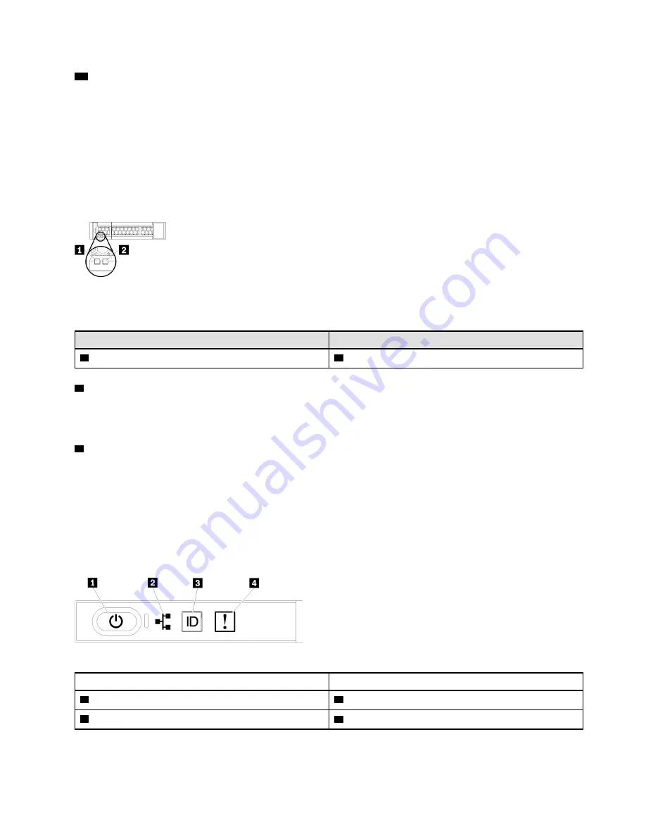
Drive LEDs
Figure 6 “Drive LEDs” on page 27 illustrates the LEDs on each drive.
Figure 6. Drive LEDs
Table 27. Drive LEDs
Callout
Callout
1
Drive activity LED (green)
2
Drive status LED (yellow)
1
Drive activity LED (green):
Each hot-swap drive comes with an activity LED. If the LED is lit, it indicates that the drive is powered, but
not actively reading or writing data. If the LED is flashing, the drive is being accessed.
2
Drive status LED (yellow):
These LEDs are on SAS or SATA hard disk drives and solid-state drives. When one of these LEDs is lit, it
indicates that the drive has failed. When this LED is flashing slowly (one flash per second), it indicates that
the drive is being rebuilt. When the LED is flashing rapidly (three flashes per second), it indicates that the
controller is identifying the drive.
Front operator panel
The following illustration shows the controls and LEDs on the front operator panel.
Table 28. Operator panel front controls and indicators
Callout
Callout
1
Power button and power LED
3
System ID button/LED
2
Network activity LED
4
System-error LED
.
27
Summary of Contents for ThinkSystem SR950
Page 1: ...ThinkSystem SR950 Setup Guide Machine Types 7X12 7X11 and 7X13 ...
Page 55: ...Figure 22 Server components Chapter 2 Server components 51 ...
Page 276: ...272 ThinkSystem SR950 Setup Guide ...
Page 282: ...278 ThinkSystem SR950 Setup Guide ...
Page 286: ...282 ThinkSystem SR950 Setup Guide ...
Page 389: ......
Page 390: ......


