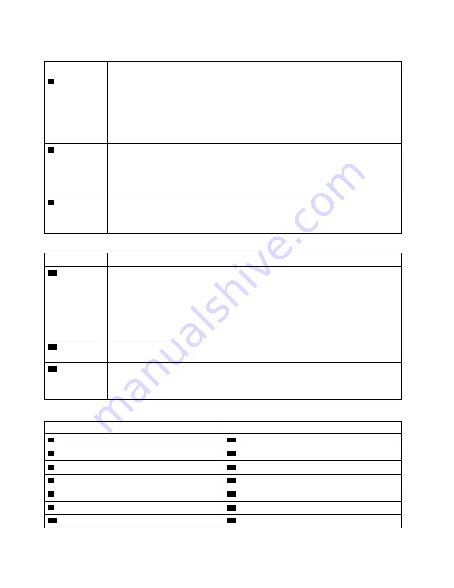
Table 32. Power supply LEDs
LED
Description
1
Input status
(AC) (green)
The input status LED can be in one of the following states:
•
Off:
The power supply is not receiving the correct input power: either the power supply is not
correctly connected to the power source, the power source is not outputting power, or the
power source output does not meet the power supply input requirements (for example, a
1600-watt power supply will not run off of 120 vac input).
•
On:
The power supply is receiving the correct input power and the power supply is operating
normally.
2
Output status
(DC) (green)
The output status LED can be in one of the following states:
•
Off:
The server is powered off (not connected to input power), the power supply is not working
correctly (Fault LED is on), or the system has overloaded the power supply (Fault LED is Off).
•
On:
The server is connected to input power (server powered on or in standby) and the power
supply is working normally.
3
Fault LED
(yellow)
•
Off:
The power supply is working correctly. If the Output status (DC) LED is also off and the
system will not power on, the system is overloading the power supply.
•
On:
The power supply has failed. Replace the power supply.
Table 33. Status LEDs
LED
Description
19
Power LED
(green)
The states of the power LED are as follows:
Off:
Power is not present or the power supply, or the LED itself has failed.
Flashing rapidly (4 times per second):
The server is turned off and is not ready to be turned
on. The power button is disabled. This will last approximately 5 to 10 seconds.
Flashing slowly (once per second):
The server is turned off and is ready to be turned on.
You can press the power button to turn on the server.
On:
The server is turned on.
20
System ID LED
(blue)
Use this blue LED to visually locate the server among other servers. You can use Lenovo XClarity
Administrator to light this LED remotely.
21
System error
LED (yellow)
When this yellow LED is lit, it indicates that a system error has occurred. A system-error LED is
also on the front operator information panel. Messages on the LCD system information display
panel and LEDs on other server components might also be lit to help isolate the error. This LED is
controlled by the Lenovo XClarity Controller.
Table 34. Adapter LEDs
Callout
Callout
4
Riser 1 to 4 fault LED
15
Adapter 15 fault LED
5
Adapter 1 fault LED
16
Adapter 16 fault LED
6
Adapter 2 fault LED
17
Adapter 17 fault LED
7
Adapter 3 fault LED
18
Riser 16 through 17 fault LED
8
Adapter 4 fault LED
22
3v fault (system battery) LED
9
Riser 10 to 15 fault LED
23
I/O-board fault LED
10
Adapter 10 fault LED
24
LOM adapter fault LED
34
ThinkSystem SR950 Setup Guide
Summary of Contents for ThinkSystem SR950
Page 1: ...ThinkSystem SR950 Setup Guide Machine Types 7X12 7X11 and 7X13 ...
Page 55: ...Figure 22 Server components Chapter 2 Server components 51 ...
Page 276: ...272 ThinkSystem SR950 Setup Guide ...
Page 282: ...278 ThinkSystem SR950 Setup Guide ...
Page 286: ...282 ThinkSystem SR950 Setup Guide ...
Page 389: ......
Page 390: ......


