Watch the procedure
. A video of the installation process is available:
•
•
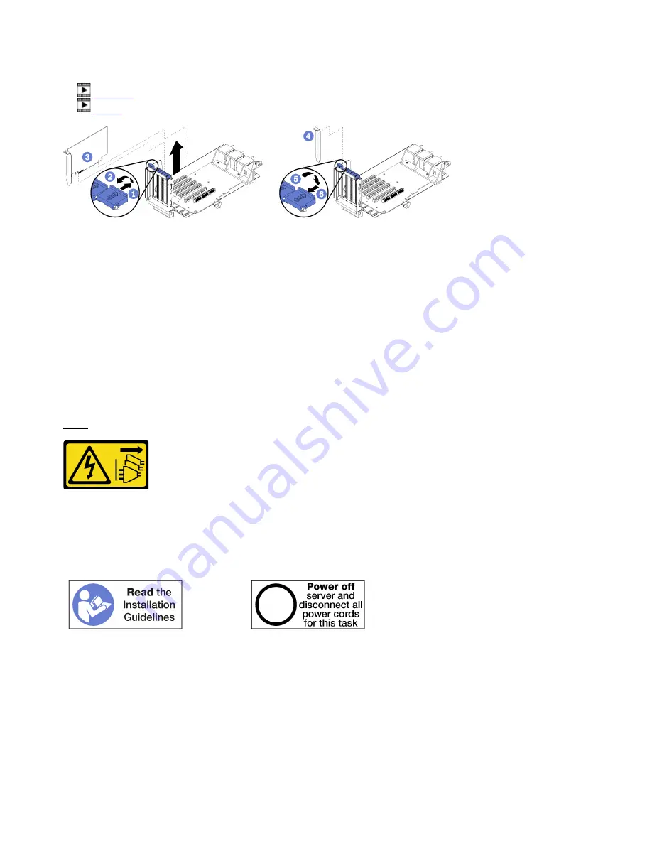
Figure 66. Adapter removal (slot 1 to 4)
Step 1. Open the retention latch.
Step 2. Disengage the adapter from its connector on the riser and lift the adapter from the riser.
After you remove the adapter:
If you are instructed to return the adapter, follow all packaging instructions, and use any packaging materials
for shipping that are supplied to you.
Remove a PCIe adapter from slot 5 to 8
PCIe adapters in slot 5 to 8 are in the I/O tray that is accessed from the rear of the server. After removing the
I/O tray from the chassis, remove the adapter from the I/O tray.
S002
CAUTION:
The power-control button on the device and the power switch on the power supply do not turn off the
electrical current supplied to the device. The device also might have more than one power cord. To
remove all electrical current from the device, ensure that all power cords are disconnected from the
power source.
CAUTION:
Make sure that all server power cords are disconnected from their power sources before performing
this procedure.
Before you remove an adapter from slot 5 to 8:
1. Disconnect and label all cables connected to adapters in the I/O tray; then, remove the I/O tray. See
“Remove the I/O tray” on page 334.
2. Remove the riser for slot 1 to 4 (riser 1) to access the adapter connectors in the I/O tray. See “Remove
the riser for slot 1 to 4 (riser 1)” on page 358.
294
ThinkSystem SR950 Setup Guide
Summary of Contents for ThinkSystem SR950
Page 1: ...ThinkSystem SR950 Setup Guide Machine Types 7X12 7X11 and 7X13 ...
Page 55: ...Figure 22 Server components Chapter 2 Server components 51 ...
Page 276: ...272 ThinkSystem SR950 Setup Guide ...
Page 282: ...278 ThinkSystem SR950 Setup Guide ...
Page 286: ...282 ThinkSystem SR950 Setup Guide ...
Page 389: ......
Page 390: ......


