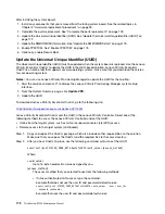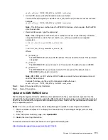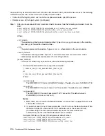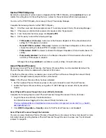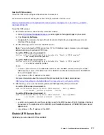
Physical Presence must be asserted if you are going to enable UEFI Secure Boot. See “Assert Physical
Presence” on page 176.
For information about accessing the Lenovo XClarity Controller interface, see:
There are two methods available to enable UEFI Secure Boot:
• From Lenovo XClarity Provisioning Manager
To enable UEFI Secure Boot from Lenovo XClarity Provisioning Manager:
1. Start the server and when prompted, press F1 to display Lenovo XClarity Provisioning Manager.
2. If the power-on Administrator password is required, enter the password.
3. From the UEFI Setup page, click
System Settings
➙
Security
➙
Secure Boot
.
4. Enable Secure Boot and save the settings.
• From Lenovo XClarity Essentials OneCLI
To enable UEFI Secure Boot from Lenovo XClarity Essentials OneCLI:
1. Download and install Lenovo XClarity Essentials OneCLI.
To download Lenovo XClarity Essentials OneCLI, go to the following site:
https://datacentersupport.lenovo.com/solutions/HT116433
2. Run the following command to enable Secure Boot:
OneCli.exe config set SecureBootConfiguration.SecureBootSetting Enabled --override
--bmc
<userid>
:
<password>
@
<ip_address>
where:
–
<userid>:<password>
are the credentials used to access the BMC (Lenovo XClarity Controller
interface) of your server. The default user ID is USERID, and the default password is PASSW0RD
(zero, not an uppercase o)
–
<ip_address>
is the IP address of the BMC.
For more information about the Lenovo XClarity Essentials OneCLI sseett command, see:
http://sysmgt.lenovofiles.com/help/topic/toolsctr_cli_lenovo/onecli_r_set_command.html
Complete the parts replacement
Use this information to complete the parts replacement.
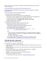
To complete the parts replacement, do the following:
1. Ensure that all components have been reassembled correctly and that no tools or loose screws are left
inside your server.
2. Properly route and secure the cables in the server. Refer to the cable connecting and routing information
for each component.
3. If you have removed the top cover, reinstall it. See “Install the server cover” on page 68.
4. Reconnect external cables and power cords to the server.
Attention:
To avoid component damage, connect the power cords last.
5. Update the server configuration if necessary.
• Download and install the latest device drivers:
http://datacentersupport.lenovo.com
178
ThinkSystem ST550 Maintenance Manual
Summary of Contents for ThinkSystem ST550 7X09
Page 1: ...ThinkSystem ST550 Maintenance Manual Machine Types 7X09 and 7X10 ...
Page 8: ...vi ThinkSystem ST550 Maintenance Manual ...
Page 36: ...28 ThinkSystem ST550 Maintenance Manual ...
Page 188: ...180 ThinkSystem ST550 Maintenance Manual ...
Page 206: ...198 ThinkSystem ST550 Maintenance Manual ...
Page 210: ...202 ThinkSystem ST550 Maintenance Manual ...
Page 219: ......
Page 220: ......

