50
Lenovo V310-14ISK/Lenovo V310-15ISK
Hardware Maintenance Manual
1090 Fan and heat sink assembly
For access, remove these FRUs in order:
• “1010 Removable module (on select models)” on page 32
• “1020 Base cover” on page 35
• “1030 Battery pack” on page 39
• “1040 Hard disk drive” on page 40
• “1050 PCI Express Mini Card for wireless LAN” on page 42
• “1070 ODD Board and 2nd battery board (Lenovo V310-15ISK)” on page 45
• “1080 USB board and fingerprint reader module” on page 47
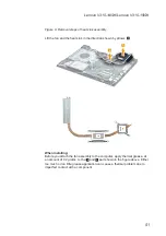
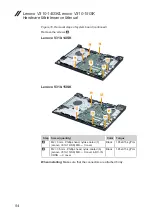
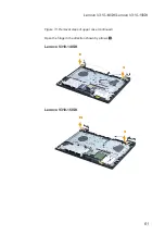
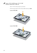
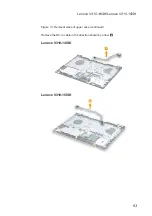
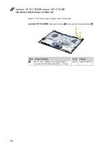
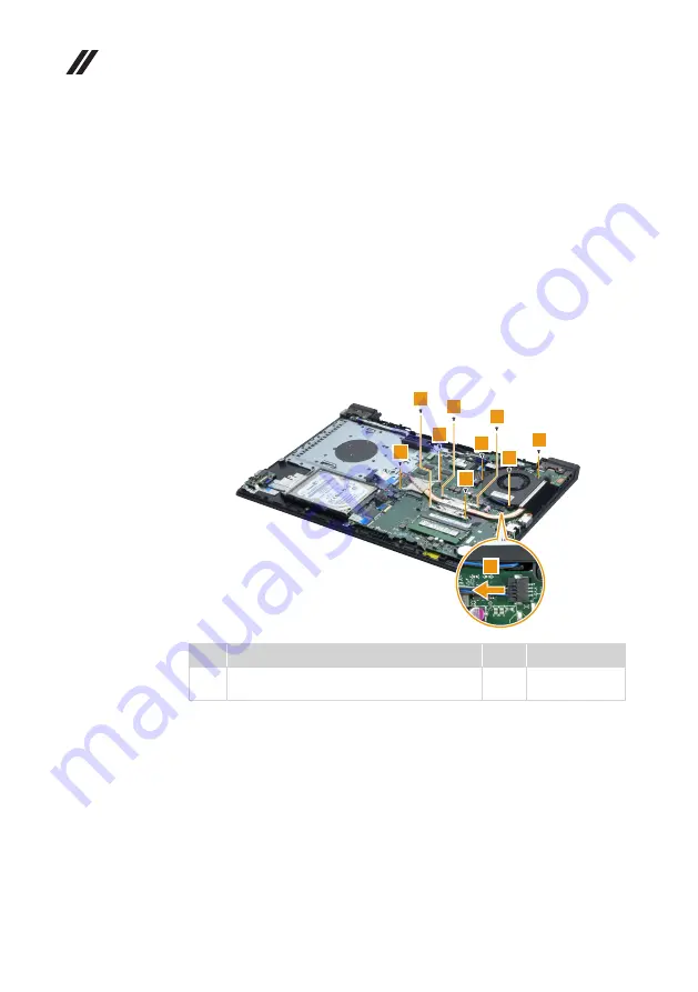
Figure 9. Removal steps of heat sink assembly
Unplug the fan connector in the direction shown by arrow
1
. Remove the
screws
2
.
1
2
2
2
2
2
2
2
2
2
Step Screw (quantity)
Color Torque
2
M2 × 3 mm, Phillips head, nylok-coated (9)
Fan and heat sink
→
MB
Black
1.85±0.15 kgf*cm

