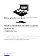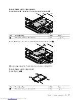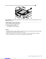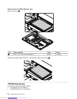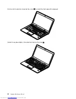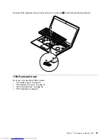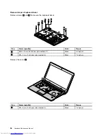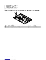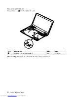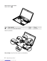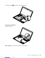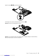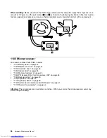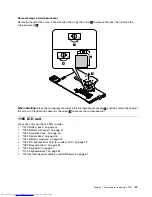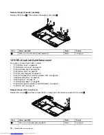
Detach the connectors.
7
6
9
8
4
5
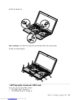
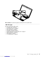
When installing:
Ensure that the connectors are attached firmly to the system board.
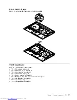
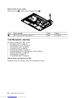
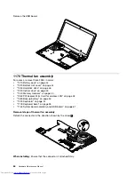
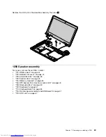
Remove the keyboard bezel.
10
10
10
10
10
10
10
10
10
11
1120 Fingerprint board and LED board
For access, remove these FRUs in order:
•
“1010 Battery pack” on page 44
•
“1020 Bottom slot cover” on page 44
Chapter 7
.
Removing or replacing a FRU
55
Summary of Contents for V480
Page 1: ...Hardware Maintenance Manual Lenovo V480 and V480c ...
Page 4: ...ii Hardware Maintenance Manual ...
Page 6: ...iv Hardware Maintenance Manual ...
Page 11: ...DANGER DANGER DANGER DANGER DANGER Chapter 1 Safety information 5 ...
Page 12: ...DANGER 6 Hardware Maintenance Manual ...
Page 13: ...Chapter 1 Safety information 7 ...
Page 14: ...PERIGO PERIGO PERIGO PERIGO PERIGO PERIGO 8 Hardware Maintenance Manual ...
Page 15: ...PERIGO PERIGO DANGER DANGER DANGER Chapter 1 Safety information 9 ...
Page 16: ...DANGER DANGER DANGER DANGER DANGER VORSICHT 10 Hardware Maintenance Manual ...
Page 17: ...VORSICHT VORSICHT VORSICHT VORSICHT Chapter 1 Safety information 11 ...
Page 18: ...VORSICHT VORSICHT VORSICHT 12 Hardware Maintenance Manual ...
Page 19: ...Chapter 1 Safety information 13 ...
Page 20: ...14 Hardware Maintenance Manual ...
Page 21: ...Chapter 1 Safety information 15 ...
Page 22: ...16 Hardware Maintenance Manual ...
Page 23: ...Chapter 1 Safety information 17 ...
Page 24: ...18 Hardware Maintenance Manual ...
Page 26: ...20 Hardware Maintenance Manual ...
Page 27: ...Chapter 1 Safety information 21 ...
Page 28: ...22 Hardware Maintenance Manual ...
Page 29: ...Chapter 1 Safety information 23 ...
Page 30: ...24 Hardware Maintenance Manual ...
Page 31: ...Chapter 1 Safety information 25 ...
Page 32: ...26 Hardware Maintenance Manual ...
Page 38: ...32 Hardware Maintenance Manual ...
Page 42: ...36 Hardware Maintenance Manual ...
Page 84: ...78 Hardware Maintenance Manual ...
Page 113: ......

