V520S
User Guide and
Hardware Maintenance Manual
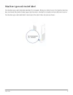
Machine Type (MT):
10NM, 10NN
Energy Star MT:
10NM, 10NN
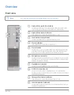
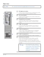
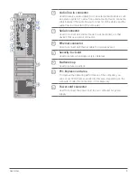
Locations of indicators,
connectors, and
controls provided on
your computer
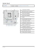
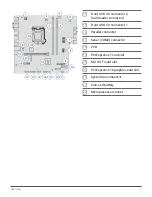
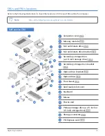
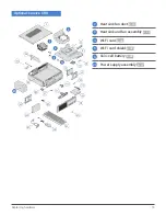
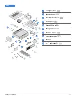
Locations of the
replaceable parts on
your computer
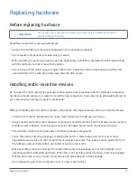
Replacing instructions
for Field Replaceable
Units (FRUs) (for
technicians only)
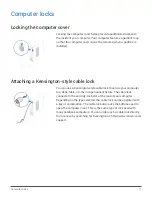
Locking devices for
your computer
Replacing instructions
for Customer
Replaceable Units
(CRUs)


