background image

Keyboard

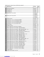
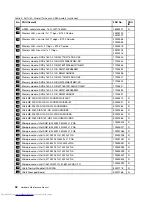
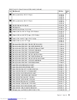
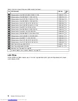
Table 7. Parts list - Keyboard (Dafon)

Language

FRU No.

CRU
ID

Arabic

25204266
25204356

N

Belgian

25204274
25204364

N

Brazilian Portuguese

25204267
25204357

N

Bulgarian

25204280
25204370

N

French, English

25204260
25204350

N

Czech, Slovak

25204279
25204369

N

Swedish, Finnish, Danish, Norwegian

25204273
25204363

N

Dutch

25204269
25204359

N

French

25204264
25204354

N

German

25204265
25204355

N

Greek

25204270
25204360

N

Hebrew

25204271
25204361

N

Hungarian

25204272
25204362

N

Icelandic

25204275
25204365

N

Indian

25204281
25204371

N

Italian

25204254
25204344

N

Korean

25204261
25204351

N

Latin

25204259
25204349

N

Portuguese

25204258
25204348

N

Russian

25204263
25204353

N

Slovenian

25204276
25204366

N

98

Hardware Maintenance Manual

Summary of Contents for V580

Page 1: ...Hardware Maintenance Manual Lenovo V580 and V580c ...

Page 2: ...under Appendix A Notices on page 107 Third Edition July 2012 Copyright Lenovo 2012 LIMITED AND RESTRICTED RIGHTS NOTICE If data or software is delivered pursuant a General Services Administration GSA contract use reproduction or disclosure is subject to restrictions set forth in Contract No GS 35F 05925 ...

Page 3: ...us indicators 38 Fn key combinations 41 Chapter 6 FRU replacement notices 43 Screw notices 43 Chapter 7 Removing and replacing a FRU 45 General guidelines 45 1010 Battery pack 46 1020 Bottom slot cover 46 1030 Optical drive or blank bezel 47 1040 Memory modules 49 1050 Hard disk drive assembly 50 1060 PCI Express Mini Card for wireless LAN 52 1070 mSATA solid state drive 54 1080 Backup battery 55 ...

Page 4: ...ii Hardware Maintenance Manual ...

Page 5: ...guidelines and safety information required for servicing computers The product specific sections include service reference and product specific parts information Important This manual is intended only for trained service technicians who are familiar with Lenovo products Use this manual to troubleshoot problems effectively Before servicing a Lenovo product be sure to read all the information under ...

Page 6: ...iv Hardware Maintenance Manual ...

Page 7: ...t unsafe Before you start the machine make sure that other service technicians and the customer s personnel are not in a hazardous position Place removed covers and other parts in a safe place away from all personnel while you are servicing the machine Keep your toolcase away from walk areas so that other people will not trip over it Do not wear loose clothing that can be trapped in the moving par...

Page 8: ...ent keep the other hand in your pocket or behind your back Attention An electrical shock can occur only when there is a complete circuit By observing the above rule you may prevent a current from passing through your body When using testers set the controls correctly and use the approved probe leads and accessories for that tester Stand on suitable rubber mats obtained locally if necessary to insu...

Page 9: ...heck exterior covers for damage loose broken or sharp edges 2 Power off the computer Disconnect the power cord 3 Check the power cord for a A third wire ground connector in good condition Use a meter to measure third wire ground continuity for 0 1 ohm or less between the external ground pin and the frame ground b The power cord should be the type specified in the parts list c Insulation must not b...

Page 10: ...ce requirement Note The use of a grounding system to guard against ESD damage is desirable but not necessary Attach the ESD ground clip to any frame ground ground braid or green wire ground When working on a double insulated or battery operated system use an ESD common ground or reference point You can use coax or connector outside shells on these systems Use the round ground prong of the ac plug ...

Page 11: ...DANGER DANGER DANGER DANGER DANGER Chapter 1 Safety information 5 ...

Page 12: ...DANGER 6 Hardware Maintenance Manual ...

Page 13: ...Chapter 1 Safety information 7 ...

Page 14: ...PERIGO PERIGO PERIGO PERIGO PERIGO PERIGO 8 Hardware Maintenance Manual ...

Page 15: ...PERIGO PERIGO DANGER DANGER DANGER Chapter 1 Safety information 9 ...

Page 16: ...DANGER DANGER DANGER DANGER DANGER VORSICHT 10 Hardware Maintenance Manual ...

Page 17: ...VORSICHT VORSICHT VORSICHT VORSICHT Chapter 1 Safety information 11 ...

Page 18: ...VORSICHT VORSICHT VORSICHT 12 Hardware Maintenance Manual ...

Page 19: ...Chapter 1 Safety information 13 ...

Page 20: ...14 Hardware Maintenance Manual ...

Page 21: ...Chapter 1 Safety information 15 ...

Page 22: ...16 Hardware Maintenance Manual ...

Page 23: ...Chapter 1 Safety information 17 ...

Page 24: ...18 Hardware Maintenance Manual ...

Page 25: ...ual translations The laser compliance statements in this section are provided in the following languages English Arabic Brazilian Portuguese French German Hebrew Japanese Korean Spanish Traditional Chinese Chapter 1 Safety information 19 ...

Page 26: ...20 Hardware Maintenance Manual ...

Page 27: ...Chapter 1 Safety information 21 ...

Page 28: ...22 Hardware Maintenance Manual ...

Page 29: ...Chapter 1 Safety information 23 ...

Page 30: ...24 Hardware Maintenance Manual ...

Page 31: ...Chapter 1 Safety information 25 ...

Page 32: ...26 Hardware Maintenance Manual ...

Page 33: ...product number Search through the product auto detect function Search by product category 3 Follow the directions on the screen and install the necessary software Notes If you need to improve the computer performance you also could download and install the latest BIOS utility from the Support Web site Do not try to update the BIOS settings for any computer unless you have been trained and certifie...

Page 34: ...uipment Directive 2002 95 EC is a European Union legal requirement affecting the global electronics industry RoHS requirements must be implemented on Lenovo products placed on the market after June 2006 Products on the market before June 2006 are not required to have RoHS compliant parts If the original FRU parts are non compliant the replacement parts also can be non compliant That is if the orig...

Page 35: ...ctive FRU What to do first When you do return a FRU you must include the following information in the parts exchange form or parts return form that you attach to it 1 Name and phone number of service technician 2 Date of service 3 Date on which the machine failed 4 Date of purchase 5 Procedure index and page number in which the failing FRU was detected 6 Failing FRU name and part number 7 Machine ...

Page 36: ...t the battery pack supplies power when you turn on the computer If you suspect a power problem see the appropriate one of the following power supply checkouts Checking the ac power adapter on page 30 Checking operational charging on page 31 Checking the battery pack on page 31 Checking the ac power adapter You are here because the computer fails only when the ac power adapter is used If the power ...

Page 37: ...ormation on the Windows operating system do the following Windows 7 Launch the Power Manager program and click the Battery tab Windows 8 Press the recovery button to launch the Lenovo Solution Center program and then click Battery Press Fn Esc to launch the Lenovo Experience program and then click Battery Health To check the battery pack do the following 1 Turn off the computer and disconnect the ...

Page 38: ...32 Hardware Maintenance Manual ...

Page 39: ... to restore the computer settings all the data you have stored on the hard disk drive will be deleted and the computer settings will be restored to the factory default settings During the restoring process you will be given the option to save one or more files currently on the hard disk drive to other media before the data is deleted Windows 8 The preinstalled Windows recovery program enables you ...

Page 40: ...hree power management modes screen blank sleep and hibernation Screen blank mode In the following circumstances the computer goes into screen blank mode The time set on the Turn off monitor timer on the Windows 7 operating system expires To end screen blank mode and resume normal operation press any key You have pressed Fn F2 To end screen blank mode and resume normal operation press Fn F2 Sleep m...

Page 41: ...auses the system to go into hibernation mode perform that action Closing the lid Pressing the power button Also the computer goes into hibernation mode automatically in either of the following conditions If a hibernation time has been set on the timer and if the user does not do any operation with the keyboard the hard disk drive the parallel connector or the diskette drive within that time If the...

Page 42: ...36 Hardware Maintenance Manual ...

Page 43: ...play the charms Then click Settings PC info Memory Double data rate 3 DDR3 synchronous dynamic random access memory SDRAM Storage device 2 5 inch 7 mm height or 9 5 mm height hard disk drive mSATA solid sate drive Note If the computer is equipped with both a hard disk drive and an mSATA solid state drive do not use the mSATA solid state drive as a bootable device The mSATA solid state drive is use...

Page 44: ...7 mm Rambo optical drive on some models Wireless features Integrated wireless LAN Integrated WiMAX 10 100 1000 Mbps Ethernet communication Security feature Fingerprint reader Status indicators This topic presents the system status indicators that show the status of the computer Status indicators V580 5 1 2 3 4 38 Hardware Maintenance Manual ...

Page 45: ...rive errors 4 Active Protection System APS status indicator White The Active Protection System program is enabled Off The Active Protection System program is disabled 5 Power and battery status indicator Solid green The battery charge level is between 80 and 100 or the battery discharge level is between 20 and 100 Slow blinking green The battery charge level is between 20 and 80 and charging is co...

Page 46: ...e computer When the indicator is on do not move the computer Sudden physical shock might cause drive errors 4 Power and battery status indicator Solid green The battery charge level is between 80 and 100 or the battery discharge level is between 20 and 100 Slow blinking green The battery charge level is between 20 and 80 and charging is continuing When the battery charge level reaches 80 the batte...

Page 47: ...rnal monitor Fn F5 Enables or disables the built in wireless networking features Fn F6 Enables or disables the touch pad Fn F9 Multimedia control Start Pause Fn F10 Multimedia control Stop Fn F11 Multimedia control Skip to the previous track Fn F12 Multimedia control Skip to the next track Fn Insert Has the same function as the ScrLk key on a conventional keyboard Fn PrtSc Has the same function as...

Page 48: ...42 Hardware Maintenance Manual ...

Page 49: ...uctions to find the manual for your product You might be required to return the defective CRU When return is required 1 return instructions a prepaid shipping label and a container will be included with the replacement CRU and 2 you might be charged for the replacement CRU if Lenovo does not receive the defective CRU within thirty 30 days of your receipt of the replacement CRU See your Lenovo Limi...

Page 50: ... screws for replacements If you have a torque screwdriver tighten all screws firmly to the torque specified in the screw information table for each step Ensure that torque screw drivers are calibrated correctly following country specifications 44 Hardware Maintenance Manual ...

Page 51: ...erve the following general guidelines 1 Do not try to service any computer unless you have been trained and certified An untrained person runs the risk of damaging parts 2 Before replacing any FRU review Chapter 6 FRU replacement notices on page 43 3 Begin by removing any FRUs that have to be removed before replacing the failing FRU Any such FRUs are listed at the beginning of each FRU replacement...

Page 52: ...explode Unlock the manual battery latch 1 Hold the right battery latch in the unlocked position and then remove the battery pack 2 2 1 2 When installing Install the battery pack in the slot Ensure that the battery latches are in the locked position 1020 Bottom slot cover For access remove this FRU 1010 Battery pack on page 46 46 Hardware Maintenance Manual ...

Page 53: ...ated 2 Black 1 85 kgf cm 1030 Optical drive or blank bezel For access remove these FRUs in order 1010 Battery pack on page 46 1020 Bottom slot cover on page 46 Removal steps of optical drive or blank bezel Remove the screw 1 1 Step Screw quantity Color Torque 1 M2 3 mm flat head nylon coated 1 Black 1 85 kgf cm Chapter 7 Removing and replacing a FRU 47 ...

Page 54: ...on shown by the arrow 3 to remove the drive 3 2 Removal steps of optical drive bezel and optical drive bracket Remove the optical drive bezel in the direction shown by the arrow in the following illustrations For Lenovo V580 models For Lenovo V580c models 48 Hardware Maintenance Manual ...

Page 55: ...2 3 mm flat head nylon coated 1 Black 1 85 kgf cm For Lenovo V580c models 1 1 2 Step Screw quantity Color Torque 1 M2 3 mm flat head nylon coated 2 Black 1 85 kgf cm 1040 Memory modules For access remove these FRUs in order 1010 Battery pack on page 46 1020 Bottom slot cover on page 46 Chapter 7 Removing and replacing a FRU 49 ...

Page 56: ...y module is to be installed on the computer you are servicing the memory module must be installed in SLOT 0 a lower slot but not in SLOT 1 b upper slot a b 1050 Hard disk drive assembly For access remove these FRUs in order 1010 Battery pack on page 46 1020 Bottom slot cover on page 46 Attention Do not drop the drive or apply any physical shock to it The drive is sensitive to physical shock Improp...

Page 57: ...by the arrow 2 2 1 Step Screw quantity Color Torque 1 M2 3 mm flat head nylon coated 1 Black 1 85 kgf cm Remove the hard disk drive from the slot in the direction shown by the arrow 3 3 When installing Ensure that the hard disk drive connector is attached firmly Chapter 7 Removing and replacing a FRU 51 ...

Page 58: ... 1 M3 4 mm flat head nylon coated 4 Black 4 0 kgf cm Remove the hard disk drive bracket in the direction shown by the arrow 2 2 1060 PCI Express Mini Card for wireless LAN For access remove these FRUs in order 1010 Battery pack on page 46 1020 Bottom slot cover on page 46 52 Hardware Maintenance Manual ...

Page 59: ...nplug them in the direction of the arrows Then remove the screw 2 2 1 1 Step Screw quantity Color Torque 2 M2 3 mm flat head nylon coated 1 Black 1 85 kgf cm Remove the PCI Express Mini Card for wireless LAN in the direction shown by the arrow 3 3 When installing Plug the black cable into the main connector and the white cable into the auxiliary connector Chapter 7 Removing and replacing a FRU 53 ...

Page 60: ...sical shock Improper handling can cause damage and permanent loss of data Before removing the drive have the user make a backup copy of all the information on it if possible Never remove the drive while the computer is operating or in suspend mode Removal steps of mSATA solid state drive Remove the screw 1 1 Step Screw quantity Color Torque 1 M2 3 mm flat head nylon coated 1 Black 1 85 kgf cm 54 H...

Page 61: ...arrow 2 2 1080 Backup battery Removal steps of backup battery DANGER Use only the battery specified in the parts list for your computer Any other battery could ignite or explode Pry the backup battery out using a screwdriver Chapter 7 Removing and replacing a FRU 55 ...

Page 62: ...hen installing Ensure that the screws have been fastened to secure the keyboard Step Screw quantity Color Torque 1 M2 5 8 mm flat head nylon coated 3 Black 4 0 kgf cm Insert a polyester film into the front edge of the keyboard and then push the polyester film in the direction shown by the arrow 2 to unlatch the front edge of the keyboard 56 Hardware Maintenance Manual ...

Page 63: ...Detach the keyboard lightly in the direction shown by the arrow 3 3 Chapter 7 Removing and replacing a FRU 57 ...

Page 64: ...ector 5 6 4 When installing Ensure that the keyboard connector is attached firmly 1100 Keyboard bezel For access remove these FRUs in order 1010 Battery pack on page 46 1020 Bottom slot cover on page 46 1030 Optical drive or blank bezel on page 47 1090 Keyboard on page 56 58 Hardware Maintenance Manual ...

Page 65: ...1 1 2 2 2 Step Screw quantity Color Torque 1 M2 5 8 mm flat head nylon coated 10 Black 4 0 kgf cm 2 M2 3 mm flat head nylon coated 3 Silver 1 85 kgf cm Remove the screws 3 3 3 3 Step Screw quantity Color Torque 3 M2 5 mm flat head nylon coated 3 Silver 1 85 kgf cm Chapter 7 Removing and replacing a FRU 59 ...

Page 66: ...nsure that all the connectors are attached firmly In steps 12 release the keyboard bezel from the frame using a plastic pry tool as shown in the following illustration Then remove the keyboard bezel in the direction shown by the arrow 13 12 12 12 12 12 12 12 12 12 13 60 Hardware Maintenance Manual ...

Page 67: ...al steps of fingerprint bracket and fingerprint board Remove the screw 1 and then remove the fingerprint board as shown in the following illustration For Lenovo V580 models 3 2 3 1 For Lenovo V580c models 3 2 3 1 Step Screw quantity Color Torque 1 M2 3 mm flat head nylon coated 1 Black 1 85 kgf cm 1120 LED board For access remove these FRUs in order 1010 Battery pack on page 46 1020 Bottom slot co...

Page 68: ...ge 56 1100 Keyboard bezel on page 58 Removal steps of LED board Peel off the mylar tape in the direction shown by the arrow 1 For Lenovo V580 models 1 For Lenovo V580c models 1 Remove the LED board in the direction shown by the arrow 2 62 Hardware Maintenance Manual ...

Page 69: ...uch pad bracket For access remove these FRUs in order 1010 Battery pack on page 46 1020 Bottom slot cover on page 46 1030 Optical drive or blank bezel on page 47 1090 Keyboard on page 56 1100 Keyboard bezel on page 58 Chapter 7 Removing and replacing a FRU 63 ...

Page 70: ...uch pad for Lenovo V580 models Remove the touch pad cable and then push the touch pad in the direction shown by the arrow 3 1 2 3 Remove the touch pad in the direction shown by the arrow 4 4 64 Hardware Maintenance Manual ...

Page 71: ...head nylon coated 1 Black 1 85 kgf cm 1140 Power board For access remove these FRUs in order 1010 Battery pack on page 46 1020 Bottom slot cover on page 46 1030 Optical drive or blank bezel on page 47 1090 Keyboard on page 56 1100 Keyboard bezel on page 58 Removal steps of power board Remove the screw 1 and then remove the power board 2 For Lenovo V580 models 2 1 Chapter 7 Removing and replacing a...

Page 72: ...r 1010 Battery pack on page 46 1020 Bottom slot cover on page 46 1030 Optical drive or blank bezel on page 47 1090 Keyboard on page 56 1100 Keyboard bezel on page 58 Removal steps of microphone assembly Detach the connector 1 and then remove the microphone assembly When installing Ensure that the connector is attached firmly to the system board 66 Hardware Maintenance Manual ...

Page 73: ...the cable 3 Then remove the I O board 4 3 2 1 1 4 Step Screw quantity Color Torque 1 M2 5 mm flat head nylon coated 2 Silver 1 85 kgf cm When installing Ensure that the cable is attached firmly to the system board 1170 USB board For access remove these FRUs in order 1010 Battery pack on page 46 1020 Bottom slot cover on page 46 1030 Optical drive or blank bezel on page 47 1090 Keyboard on page 56 ...

Page 74: ...r access remove these FRUs in order 1010 Battery pack on page 46 1020 Bottom slot cover on page 46 1030 Optical drive or blank bezel on page 47 1040 Memory modules on page 49 1050 Hard disk drive assembly on page 50 1060 PCI Express Mini Card for wireless LAN on page 52 1070 mSATA solid state drive on page 54 1080 Backup battery on page 55 1090 Keyboard on page 56 1100 Keyboard bezel on page 58 11...

Page 75: ...y Important notices for removing the system board When removing the system board bear the following in mind Be careful not to drop the system board on a bench top that has a hard surface such as metal wood or composite Avoid rough handling of any kind At every point in the process be sure not to drop or stack the system board If you put a system board down be sure to put it only on a padded surfac...

Page 76: ...80 Backup battery on page 55 1090 Keyboard on page 56 1100 Keyboard bezel on page 58 Removal steps of system board assembly Remove the screws 1 and then detach the connectors as shown in the following illustration 9 8 10 2 5 7 6 3 4 1 1 Step Screw quantity Color Torque 1 M2 5 mm flat head nylon coated 3 Silver 1 85 kgf cm When installing Ensure that all the connectors are attached firmly Detach th...

Page 77: ...For Lenovo V580 models 12 11 For Lenovo V580c models 12 11 Chapter 7 Removing and replacing a FRU 71 ...

Page 78: ...sembly on page 50 1060 PCI Express Mini Card for wireless LAN on page 52 1070 mSATA solid state drive on page 54 1080 Backup battery on page 55 1090 Keyboard on page 56 1100 Keyboard bezel on page 58 1150 Microphone assembly on page 66 1190 System board assembly on page 69 Removal steps of thermal fan assembly Detach the connector 1 1 When installing Ensure that the connector is attached firmly 72...

Page 79: ...Loosen the screws 2 to 8 2 3 4 5 7 6 8 Chapter 7 Removing and replacing a FRU 73 ...

Page 80: ...r too much or too less application of grease can cause a thermal problem due to imperfect contact with a component a b 1210 Microprocessor For access remove these FRUs in order 1010 Battery pack on page 46 1020 Bottom slot cover on page 46 1030 Optical drive or blank bezel on page 47 1040 Memory modules on page 49 1050 Hard disk drive assembly on page 50 1060 PCI Express Mini Card for wireless LAN...

Page 81: ...emove the microprocessor 2 2 2 a b 1 When installing Place the microprocessor above the microprocessor socket a and then rotate the head of the screw in the direction shown by the arrow b to secure the microprocessor 1220 LCD unit For access remove these FRUs in order 1010 Battery pack on page 46 1020 Bottom slot cover on page 46 1030 Optical drive or blank bezel on page 47 1040 Memory modules on ...

Page 82: ...Torque 1 M2 5 5 mm flat head nylon coated 4 Silver 4 0 kgf cm When installing Route the antenna cables along the cable guides As you route the cables ensure that they are not subject to any tension Tension could cause the cables to be damaged by the cable guides or a wire to be broken Ensure that the LCD connector is attached firmly and ensure that you do not pinch the antenna cables when you atta...

Page 83: ... on page 47 1040 Memory modules on page 49 1050 Hard disk drive assembly on page 50 1060 PCI Express Mini Card for wireless LAN on page 52 1070 mSATA solid state drive on page 54 1080 Backup battery on page 55 1090 Keyboard on page 56 1100 Keyboard bezel on page 58 1150 Microphone assembly on page 66 1160 I O board on page 67 1190 System board assembly on page 69 1220 LCD unit on page 75 Chapter 7...

Page 84: ...speaker assembly and base cover Remove the screws 1 Then remove the speaker assembly 2 1 1 1 1 2 2 Step Screw quantity Color Torque 1 M2 5 5 7 mm flat head nylon coated 4 Black 4 0 kgf cm 78 Hardware Maintenance Manual ...

Page 85: ...g the original location of the label on the computer and the information on the label such as the part number serial number and product key The following illustration shows the label locations on the base cover 10 11 13 1 2 3 6 7 8 4 9 5 12 1 Wireless WAN IMEI barcode label 7 Brazil wireless LAN label or wireless LAN label for United States Canada Taiwan 2 China label KCC label or MAC label 8 PPT ...

Page 86: ...CD front bezel Remove the screws 1 1 1 Step Screw quantity Color Torque 1 M2 3 5 mm flat head nylon coated 2 Black 1 85 kgf cm Remove the LCD front bezel in the direction shown by the arrows 2 2 2 2 2 When installing Ensure that all the latches are attached firmly Then secure the bezel with the screws 80 Hardware Maintenance Manual ...

Page 87: ...llowing illustration Note The integrated camera is stuck on the top center of the LCD cover 1 2 When installing Stick the integrated camera to the top center of the LCD cover and adjust the placement to ensure that the connector is attached firmly 2030 LCD panel LCD cable and hinges For access remove these FRUs in order 1010 Battery pack on page 46 1220 LCD unit on page 75 2010 LCD front bezel on ...

Page 88: ...2 1 1 1 1 1 1 2 Step Screw quantity Color Torque 1 M2 3 5 mm flat head nylon coated 6 Silver 1 85 kgf cm Turn over the LCD panel in the direction shown by the arrow 3 Then detach the LCD cable as shown in the following illustration 3 4 5 When installing Ensure that the cable is attached firmly 82 Hardware Maintenance Manual ...

Page 89: ... flat head nylon coated 4 White 1 85 kgf cm 2040 Antenna assembly and LCD rear cover For access remove these FRUs in order 1010 Battery pack on page 46 1220 LCD unit on page 75 2010 LCD front bezel on page 80 2020 Integrated camera on page 81 2030 LCD panel LCD cable and hinges on page 81 Chapter 7 Removing and replacing a FRU 83 ...

Page 90: ...he hinges in the direction shown by the arrows 1 1 1 Cable routing Route the antenna cables along the cable guides and secure the antenna boards with tape As you route the cables ensure that they are not subject to any tension Tension could cause the cables to be damaged by the cable guides or a wire to be broken 84 Hardware Maintenance Manual ...

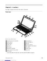
Page 91: ... 2 Wireless antennas 11 Media card reader slot 3 Status indicators1 12 Touch pad 4 Speaker right 13 Integrated microphone 5 Power jack 14 Power and battery status indicator1 6 USB connector 15 Power button 7 Optical drive or blank bezel 16 Recovery button 8 Fingerprint reader on some models 17 Speaker left 9 USB connector 1 For the description of the indicators see Status indicators V580 on page 3...

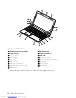
Page 92: ...tatus indicators1 12 Touch pad 4 Speaker right 13 Integrated microphone 5 Power jack 14 Power and battery status indicator1 6 USB connector 15 Power button 7 Optical drive or blank bezel 16 Recovery button 8 Fingerprint reader on some models 17 Speaker left 9 USB connector 1 For the description of the indicators see Status indicators V580c on page 40 86 Hardware Maintenance Manual ...

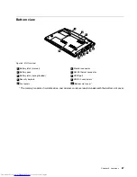
Page 93: ...nnector 2 Battery pack 7 RJ45 Ethernet connector 3 Battery latch spring loaded 8 HDMI port 4 Security keyhole 9 USB 3 0 connectors 5 Fan louvers 10 Bottom slot cover1 1 The memory modules hard disk drive and wireless cards are located underneath the bottom slot cover Chapter 8 Locations 87 ...

Page 94: ...88 Hardware Maintenance Manual ...

Page 95: ... available from Lenovo at any time upon request You can find a list of CRUs for your product in this Hardware Maintenance Manual An electronic version of this manual can be found at http www lenovo com UserManuals Follow the on screen instructions to find the manual for your product You might be required to return the defective CRU When return is required 1 return instructions a prepaid shipping l...

Page 96: ...22 20 21 j 19 18 17 16 15 i 13 14 Table 4 Parts list Overall for Lenovo V580 models No FRU Overall FRU No CRU ID a j See Miscellaneous parts on page 99 1 LCD unit see LCD FRUs on page 96 2 LA58 Power Board 90000412 N 3 LA58 Upper Case 90201175 N 90 Hardware Maintenance Manual ...

Page 97: ... 13 SATA hard disk drive 320 G 7200 rpm TSB MK3261GSY 7200PRM 9 5 mm 16200099 13 SATA hard disk drive 320 G 7200 rpm HTS725032A7E630 16200194 13 SATA hard disk drive 320 G 7200 rpm Seagate ST320LT007 7 mm 16005030 13 SATA hard disk drive 500 G 5400 rpm WD5000BPVT 08A1Y 16200118 13 SATA hard disk drive 500 G 5400 rpm WD5000BPVT 08HXZ 16200090 13 SATA hard disk drive 500 G 5400 rpm Toshiba MK5065GSX...

Page 98: ...22NQ08IAF 11200397 18 LA58 MB DIS N13P GS 2G W HDMI WO 3G BT 90000414 N 18 LA58 MB DIS N13P GS 2G W HDMI WO SBA BT 90000337 N 18 LA58 MB W8 DIS N13P GS 2G W HDMI SBA 90001562 N 18 LA58 MB W8P DIS N13P GS 2G W HDMI SBA 90001563 N 18 LA58 MB W8 DIS N13P GS 2G W HDMI WO SBA 90001564 N 18 LA58 MB W8P DIS N13P GS 2G W HDMI WO SBA 90001565 N 19 Microprocessor Intel SNB I3 2350M 2 3G 3M J1 PGA 102500018 ...

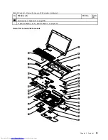
Page 99: ...inued No FRU Overall FRU No CRU ID 22 Keyboard see Keyboard on page 98 ac power adapter see ac power adapters on page 101 Overall for Lenovo V580c models 1 2 a 4 3 5 c d b 6 7 8 9 e f 10 11 g 13 12 23 22 21 20 19 18 17 16 h j 14 15 Chapter 9 Parts list 93 ...

Page 100: ...er Case 90200822 N 11 Optical drive 12 7 mm tray in Rambo DS 8A8SH 25201487 11 Optical drive 12 7 mm tray in Rambo AD 7740H 25201106 11 Optical drive 12 7 mm tray in Rambo SN 208AB 25201108 11 Optical drive 12 7 mm tray in Rambo GT50N 25201635 12 LA58C CardReader Board W Cable 90000572 N 13 LB58 Memory Door 90200816 N 14 SATA hard disk drive 320 G 5400 rpm 16200265 16200097 16200274 16200222 16200...

Page 101: ...9 Memory module DDR3 1600 2 GB SM321NH08IAF 11200396 19 Memory module DDR3 1600 4 GB M471B5273DH0 CK0 11200341 19 Memory module DDR3 1600 4 GB HMT351S6CFR8C PB 11200344 19 Memory module DDR3 1600 4 GB MT16KTF51264HZ 1G6M1 11200347 19 Memory module DDR3 1600 4 GB RMT3160ED58E9W 11200393 19 Memory module DDR3 1600 4 GB SM322NQ08IAF 11200397 20 LA58C MB UMA W SBA HDMI WO 3G BT 90000573 N 20 LA58C MB ...

Page 102: ...r Intel SNB B940 2 0G 2M Q0 PGA 102500015 N 21 Microprocessor Intel B815 1 6G Q0 2M 2cPGA 102500229 N 21 Microprocessor Intel SNB B800 1 5G Q0 2M 2c PGA 102500101 N 21 Microprocessor Intel I3 2308M 2 1G Q0 3M 2cPGA 102500351 N 21 Microprocessor Intel B820 1 7G Q0 2M 2cPGA 102500350 N 21 Microprocessor Intel I5 3210M 2 5G L1 3M 2cPGA 102500301 N 21 Microprocessor Intel I3 3110M 2 3G L1 3M 2cPGA 102...

Page 103: ...01173 N 1 LA58C LCD Bezel W Camera Hole 90201345 N 2 LA58 Hinge L R 90201174 N 3 LA58 Antenna R 90201177 N 4 LA48 Camera 1M 90200517 N 5 LA58 LCD Cover 90201172 N 5 LA58C LCD Cover WO Antenna 90201344 N 6 LA58 Antenna L 90201176 N 7 LCD panel 15 6 inch Wedge Glossy 18200114 18200158 18200157 N Chapter 9 Parts list 97 ...

Page 104: ...h Finnish Danish Norwegian 25204273 25204363 N Dutch 25204269 25204359 N French 25204264 25204354 N German 25204265 25204355 N Greek 25204270 25204360 N Hebrew 25204271 25204361 N Hungarian 25204272 25204362 N Icelandic 25204275 25204365 N Indian 25204281 25204371 N Italian 25204254 25204344 N Korean 25204261 25204351 N Latin 25204259 25204349 N Portuguese 25204258 25204348 N Russian 25204263 2520...

Page 105: ...odels on page 100 Miscellaneous parts for Lenovo V580 models Note Italicized letters in parentheses are references to the exploded view in Overall for Lenovo V580 models on page 90 Table 8 Parts list System miscellaneous parts FRU FRU no CRU ID e LB58 DC IN Bracket 90200821 N g LA48 ODD Bracket 90200518 N h LB58 ODD Bezel Rambo 90200815 N i LA48 HDD Bracket 90200520 N LA58 LCD Bezel Screw Pad 9020...

Page 106: ...3 Table 10 Parts list System miscellaneous parts FRU FRU no CRU ID c LB58 FP Bracket 90200818 N e LB58 DC IN Bracket 90200821 N f LA48 ODD Bracket 90200518 N g LB58 ODD Bezel Rambo 90200815 N h LA48 HDD Bracket 90200520 N i LB58 TP Bracket 90200820 N LA58 LCD Bezel Screw Pad 90201179 N LA58C Screw Pack 90201346 N Table 11 Parts list Cable miscellaneous parts FRU FRU no CRU ID a LB58 Power Board Ca...

Page 107: ...able 13 Parts list 2 pin 90 W ac power adapters FRU FRU no CRU ID 2 pin Eup models 36200102 36200101 36200103 2 pin EPA models 36200147 36200149 36200150 2 pin CS2 plug 36200295 36200297 36200299 Table 14 Parts list 3 pin 65 W ac power adapters FRU FRU no CRU ID 3 pin Eup models 36200096 36200097 36200098 3 pin EPA models 36200033 36200034 36200212 3 pin CS2 plug 36200288 36200290 36200292 Chapter...

Page 108: ...03VV F LP39 1 m 145000599 Australia New Zealand LINETEK LS15 H03VV F LP 23A 1 m 145000589 Brazil LINETEK LS15 H03VV F LP26A 1 m 145000596 European Union LINETEK LP 34 H03VV F LS15 1 m 145000585 China LINETEK PC323 RVV300 300 LS15 1 m 145000600 Denmark LINETEK LS15 H03VV F LP 38 1 m 145000598 Indian LINETEK PE 361 H05VV F LS15 1 m 145000592 Israel LINETEK LS15 H03VV F LP 41 1 m 145000595 Italy LINE...

Page 109: ... Longwell LP 23A LFC 3R LS 18 1 m 145000557 Brazil Longwell LP 46 H03VV F LS 18 1 m 145000564 European Union Longwell LP 34A H03VV F LS 18 1 m 145000553 China Longwell LSG 31 RVV300 300 LS 18 1 m 145000568 Denmark Longwell LP 40 H03VV F LS 18 1 m 145000566 Indian Longwell LP 67 BIS LS 18 1 m 145000560 Israel Longwell LP 41 H03VV F LS 18 1 m 145000563 Italy Longwell LP 22 H03VV F LS 18 1 m 14500055...

Page 110: ...5000532 Brazil VOLEX CH10S3 H03VV F VAC5S 1 m 145000527 European Union VOLEX M2511 HO3VV F VAC5S 1 m 145000525 China VOLEX GB10S3 RVV 300 500 VAC5S 1 m 145000538 Denmark VOLEX MP233D H03VV F VAC5S 1 m 145000534 Indian VOLEX IA6A3 IS694 VAC5S 1 m 145000536 Israel VOLEX SI16S3 H03VV F VAC5S 1 m 145000526 Italy VOLEX IT10S3 HO3VV F VAC5S 1 m 145000535 Japan VOLEX VAC5S VCTF M755 1 m 145000530 Korea V...

Page 111: ...Table 18 Parts list 3 pin power cords Volex continued Country or region FRU no CRU ID U K VOLEX MP5004 H03VV F VAC5S 1 m 145000605 U S A Volex US15S3 SPT 2 VAC5S 1 m 145000537 Chapter 9 Parts list 105 ...

Page 112: ...106 Hardware Maintenance Manual ...

Page 113: ...e publication Lenovo may make improvements and or changes in the product s and or the program s described in this publication at any time without notice The products described in this document are not intended for use in implantation or other life support applications where malfunction may result in injury or death to persons The information contained in this document does not affect or change Len...

Page 114: ...wing terms are trademarks of Lenovo in the United States other countries or both Active Protection System Lenovo OneKey Windows is a trademark of the Microsoft group of companies Intel is a trademark of Intel Corporation in the U S and or other countries Other company product or service names may be trademarks or service marks of others 108 Hardware Maintenance Manual ...

Page 115: ......

Page 116: ......

Reviews: