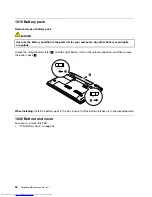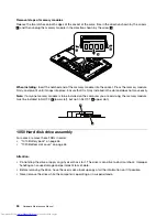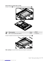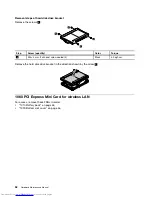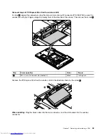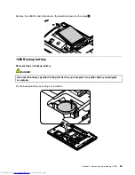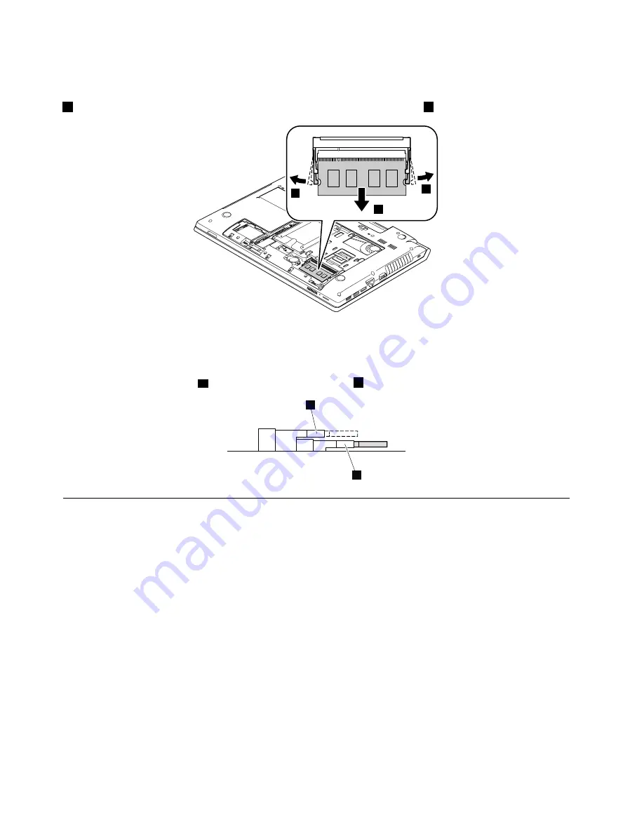
Removal steps of memory modules
Release the two latches on both edges of the socket at the same time in the direction shown by the arrows
1
, and then unplug the memory module in the direction shown by the arrow
2
.
1
1
2
When installing:
Insert the notched end of the memory module into the socket. Press the memory module
firmly, and pivot it until it snaps into place. Ensure that it is firmly installed in the slot and does not move easily.
Note:
If only one memory module is to be installed on the computer you are servicing, the memory module
must be installed in SLOT-0 (
a
lower slot), but not in SLOT-1 (
b
upper slot).
a
b
1050 Hard disk drive assembly
For access, remove these FRUs in order:
•
“1010 Battery pack” on page 46
•
“1020 Bottom slot cover” on page 46
Attention:
• Do not drop the drive or apply any physical shock to it. The drive is sensitive to physical shock. Improper
handling can cause damage and permanent loss of data.
• Before removing the drive, have the user make a backup copy of all the information on it if possible.
• Never remove the drive while the computer is operating or in suspend mode.
50
Hardware Maintenance Manual
Summary of Contents for V580
Page 1: ...Hardware Maintenance Manual Lenovo V580 and V580c ...
Page 4: ...ii Hardware Maintenance Manual ...
Page 6: ...iv Hardware Maintenance Manual ...
Page 11: ...DANGER DANGER DANGER DANGER DANGER Chapter 1 Safety information 5 ...
Page 12: ...DANGER 6 Hardware Maintenance Manual ...
Page 13: ...Chapter 1 Safety information 7 ...
Page 14: ...PERIGO PERIGO PERIGO PERIGO PERIGO PERIGO 8 Hardware Maintenance Manual ...
Page 15: ...PERIGO PERIGO DANGER DANGER DANGER Chapter 1 Safety information 9 ...
Page 16: ...DANGER DANGER DANGER DANGER DANGER VORSICHT 10 Hardware Maintenance Manual ...
Page 17: ...VORSICHT VORSICHT VORSICHT VORSICHT Chapter 1 Safety information 11 ...
Page 18: ...VORSICHT VORSICHT VORSICHT 12 Hardware Maintenance Manual ...
Page 19: ...Chapter 1 Safety information 13 ...
Page 20: ...14 Hardware Maintenance Manual ...
Page 21: ...Chapter 1 Safety information 15 ...
Page 22: ...16 Hardware Maintenance Manual ...
Page 23: ...Chapter 1 Safety information 17 ...
Page 24: ...18 Hardware Maintenance Manual ...
Page 26: ...20 Hardware Maintenance Manual ...
Page 27: ...Chapter 1 Safety information 21 ...
Page 28: ...22 Hardware Maintenance Manual ...
Page 29: ...Chapter 1 Safety information 23 ...
Page 30: ...24 Hardware Maintenance Manual ...
Page 31: ...Chapter 1 Safety information 25 ...
Page 32: ...26 Hardware Maintenance Manual ...
Page 38: ...32 Hardware Maintenance Manual ...
Page 42: ...36 Hardware Maintenance Manual ...
Page 48: ...42 Hardware Maintenance Manual ...
Page 79: ...Loosen the screws 2 to 8 2 3 4 5 7 6 8 Chapter 7 Removing and replacing a FRU 73 ...
Page 94: ...88 Hardware Maintenance Manual ...
Page 112: ...106 Hardware Maintenance Manual ...
Page 115: ......
Page 116: ......


