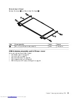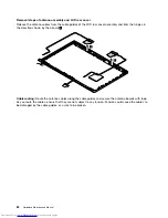
•
“1090 Keyboard” on page 56
•
“1100 Keyboard bezel” on page 58
•
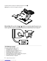
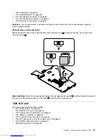
“1150 Microphone assembly” on page 66
•
“1160 I/O board” on page 67
•
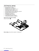
“1190 System board assembly” on page 69
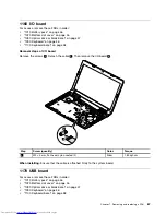
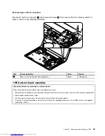
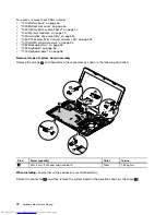
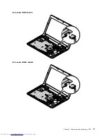
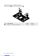
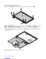
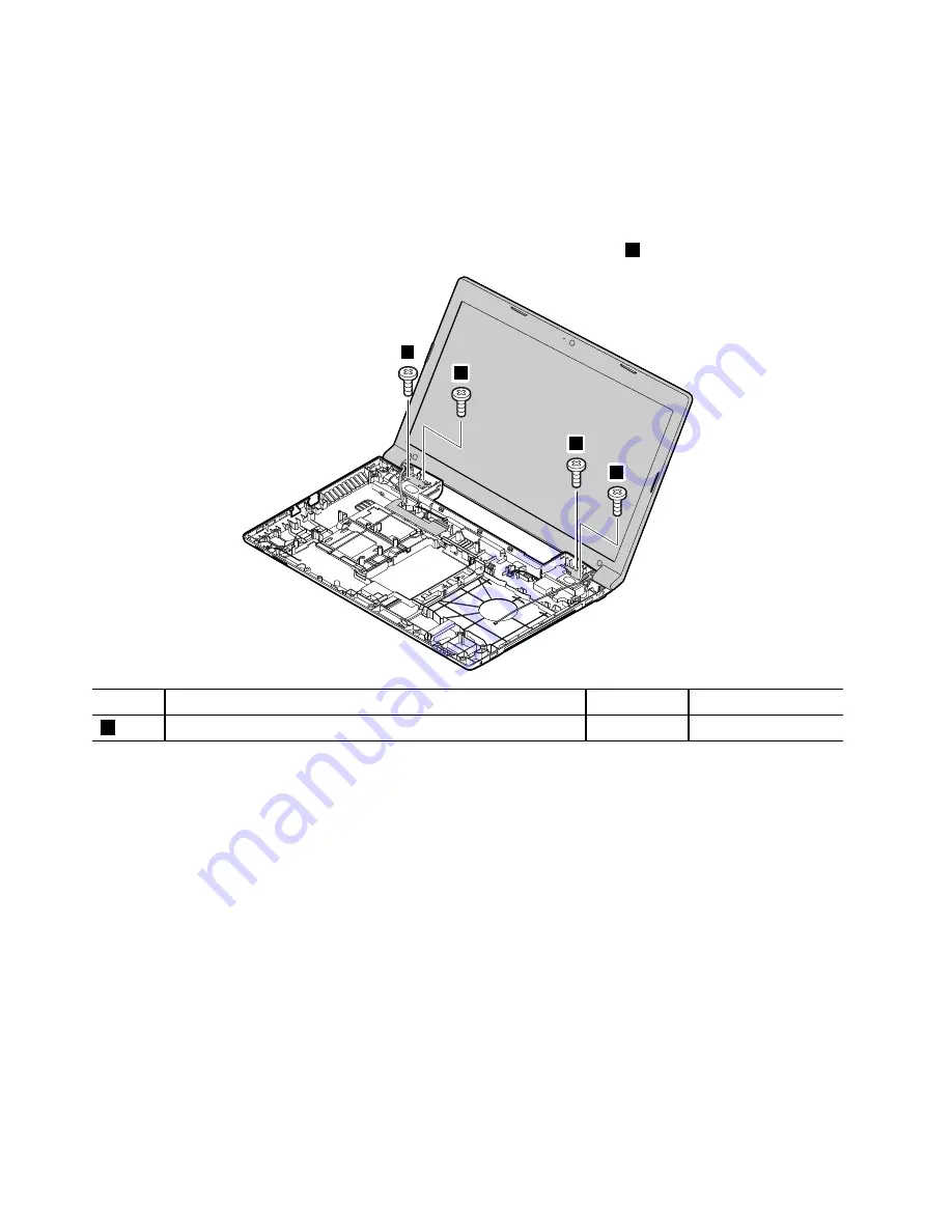
Removal steps of LCD unit
Release the antenna cables from the cable guides. Then remove the screws
1
.
1
1
1
1
Step
Screw (quantity)
Color
Torque
1
M2.5 × 5 mm, flat-head, nylon-coated (4)
Silver
4.0 kgf-cm
When installing:
• Route the antenna cables along the cable guides. As you route the cables, ensure that they are not subject
to any tension. Tension could cause the cables to be damaged by the cable guides, or a wire to be broken.
• Ensure that the LCD connector is attached firmly and ensure that you do not pinch the antenna cables
when you attach the LCD assembly. Route the LCD cable along the cable guides.
76
Hardware Maintenance Manual
Summary of Contents for V580
Page 1: ...Hardware Maintenance Manual Lenovo V580 and V580c ...
Page 4: ...ii Hardware Maintenance Manual ...
Page 6: ...iv Hardware Maintenance Manual ...
Page 11: ...DANGER DANGER DANGER DANGER DANGER Chapter 1 Safety information 5 ...
Page 12: ...DANGER 6 Hardware Maintenance Manual ...
Page 13: ...Chapter 1 Safety information 7 ...
Page 14: ...PERIGO PERIGO PERIGO PERIGO PERIGO PERIGO 8 Hardware Maintenance Manual ...
Page 15: ...PERIGO PERIGO DANGER DANGER DANGER Chapter 1 Safety information 9 ...
Page 16: ...DANGER DANGER DANGER DANGER DANGER VORSICHT 10 Hardware Maintenance Manual ...
Page 17: ...VORSICHT VORSICHT VORSICHT VORSICHT Chapter 1 Safety information 11 ...
Page 18: ...VORSICHT VORSICHT VORSICHT 12 Hardware Maintenance Manual ...
Page 19: ...Chapter 1 Safety information 13 ...
Page 20: ...14 Hardware Maintenance Manual ...
Page 21: ...Chapter 1 Safety information 15 ...
Page 22: ...16 Hardware Maintenance Manual ...
Page 23: ...Chapter 1 Safety information 17 ...
Page 24: ...18 Hardware Maintenance Manual ...
Page 26: ...20 Hardware Maintenance Manual ...
Page 27: ...Chapter 1 Safety information 21 ...
Page 28: ...22 Hardware Maintenance Manual ...
Page 29: ...Chapter 1 Safety information 23 ...
Page 30: ...24 Hardware Maintenance Manual ...
Page 31: ...Chapter 1 Safety information 25 ...
Page 32: ...26 Hardware Maintenance Manual ...
Page 38: ...32 Hardware Maintenance Manual ...
Page 42: ...36 Hardware Maintenance Manual ...
Page 48: ...42 Hardware Maintenance Manual ...
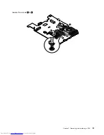
Page 79: ...Loosen the screws 2 to 8 2 3 4 5 7 6 8 Chapter 7 Removing and replacing a FRU 73 ...
Page 94: ...88 Hardware Maintenance Manual ...
Page 112: ...106 Hardware Maintenance Manual ...
Page 115: ......
Page 116: ......

