
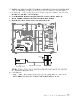


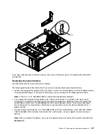


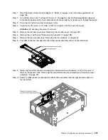


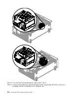

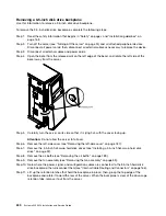

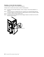


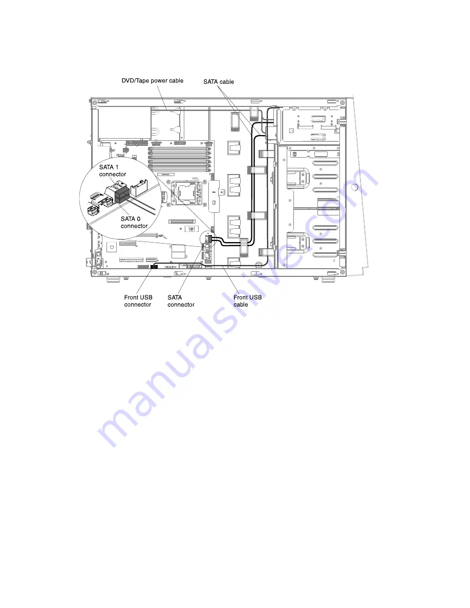
Step 11. Connect the USB cable to the front USB connector on the system board. Route the USB cable as
shown in the following illustration.
Step 12. Secure the cable with any cable clips in the server.
If you have other devices to install or remove, do so now. Otherwise, go to “Completing the installation”
on page 83.
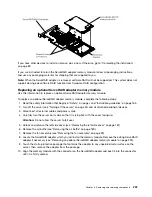
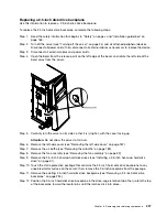
Removing a 2.5-inch disk drive backplane
Use this information to remove a 2.5-inch disk drive backplane.
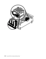
To remove the 2.5-inch disk drive backplane, complete the following steps:
Step 1.
Read the safety information that begins in “Safety” on page v and “Installation guidelines” on
page 163.
Step 2.
Turn off the server (see “Turning off the server” on page 24) and all attached peripheral devices.
Disconnect all power cords; then, disconnect all external cables as necessary to replace the device.
Step 3.
Disconnect all external cables and power cords.
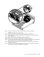
Step 4.
Open the bezel from the release point on the left edge of the bezel, and rotate the left side of the
bezel away from the server.
234
System x3300 M4 Installation and Service Guide
Summary of Contents for x3300 M4 7382
Page 1: ...System x3300 M4 Installation and Service Guide Machine Type 7382 ...
Page 6: ...iv System x3300 M4 Installation and Service Guide ...
Page 14: ...xii System x3300 M4 Installation and Service Guide ...
Page 166: ...152 System x3300 M4 Installation and Service Guide ...
Page 176: ...162 System x3300 M4 Installation and Service Guide ...
Page 704: ...690 System x3300 M4 Installation and Service Guide ...
Page 888: ...874 System x3300 M4 Installation and Service Guide ...
Page 896: ...Taiwan BSMI RoHS declaration 882 System x3300 M4 Installation and Service Guide ...
Page 906: ...892 System x3300 M4 Installation and Service Guide ...
Page 907: ......
Page 908: ......


