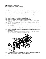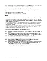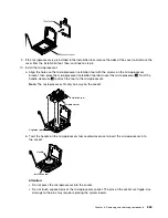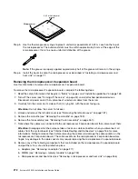
Note:
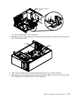
Press the microprocessor 2 expansion board connector to make sure the connector is seated
securely on the system board.
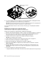
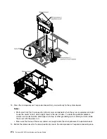
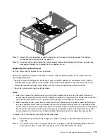
15. Connect the microprocessor 2 power cable (P4) to its connector on the system board (see “Power Cable
If you have other devices to install or remove, do so now. Otherwise, go to “Completing the installation”
on page 83.
Removing the system board
Use this information to remove the system board.
Before you remove the system board from the server, take the following steps to save data, firmware,
and configuration data:
• Record all system configuration information, such as IMM IP addresses, vital product data, and the
machine type, model number, serial number, Universally Unique Identifier, and asset tag of the server.
• Using the Advanced Settings Utility (ASU), save the system configuration to external media.
• Save the system-event log to external media.
Notes:
1. When you replace the system board, you must either update the server with the latest firmware or
restore the pre-existing firmware that the customer provides on a diskette or CD image. Make sure that
you have the latest firmware or a copy of the pre-existing firmware before you proceed.
2. Before you replace the system board, make sure that you backup any features on demand (FoD) keys
that were enabled. Remember to re-enable the features on demand (FoD) keys after installing the new
system board. For more information on Features on Demand (FoD), including instructions for automating
the activation and installation of the activation key by using ToolsCenter or Systems Director, see the
Lenovo Features on Demand User’s Guide
at https://fod.lenovo.com/lkms under the Help section.
To remove the system board, complete the following steps:
Step 1.
Read the safety information that begins in “Safety” on page v and “Installation guidelines” on
page 163.
Step 2.
Turn off the server (see “Turning off the server” on page 24) and all attached peripheral devices.
Disconnect all power cords; then, disconnect all external cables from the server.
Step 3.
Carefully turn the server on its side so that it is lying flat, with the cover facing up.
Attention:
Do not allow the server to fall over.
Step 4.
Unlock and remove the left-side cover (see “Removing the left-side cover” on page 187).
Step 5.
Remove the air baffle (see “Removing the air baffle” on page 189).
Step 6.
Remove all fan assemblies (see “Removing the fan assembly” on page 261).
Step 7.
Remove all PCI riser-card assemblies with the adapters in them (see “Removing a PCI-X riser-card
assembly” on page 224 and “Removing an adapter” on page 211).
Step 8.
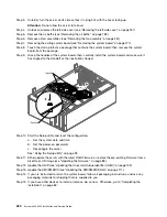
Disconnect all cables from the system board. Make a list of each cable as you disconnect it; you
can then use this as a checklist when you install the new system board.
Step 9.
Remove the DIMMs from the system board and set them aside on a static-protective surface for
reinstallation (see “Removing a memory module” on page 253).
Note:
Make a note of the location of each DIMM as you remove it, so that you can later reinstall it
in the same connector.
Removing and replacing components
277
Summary of Contents for x3300 M4 7382
Page 1: ...System x3300 M4 Installation and Service Guide Machine Type 7382 ...
Page 6: ...iv System x3300 M4 Installation and Service Guide ...
Page 14: ...xii System x3300 M4 Installation and Service Guide ...
Page 166: ...152 System x3300 M4 Installation and Service Guide ...
Page 176: ...162 System x3300 M4 Installation and Service Guide ...
Page 704: ...690 System x3300 M4 Installation and Service Guide ...
Page 888: ...874 System x3300 M4 Installation and Service Guide ...
Page 896: ...Taiwan BSMI RoHS declaration 882 System x3300 M4 Installation and Service Guide ...
Page 906: ...892 System x3300 M4 Installation and Service Guide ...
Page 907: ......
Page 908: ......


