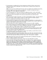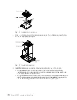
Step 2.
Turn off the server and peripheral devices and disconnect the power cords and all external cables,
if necessary.
Step 3.
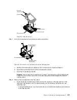
Disconnect the cables from the front video connector.
0000000000000000000000000000
0000000000000000000000000000
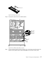
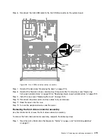
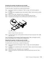
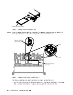
Figure 204. Front USB and video cables connection
Step 4.
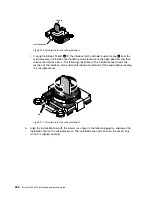
Remove the screws from the video connector assembly.
0000000000000
0000000000000
0000000000000
0000000000000
0000000000000
0000000000000
0000000000000
0000
0000
0000
0000
Figure 205. Video connector assembly screws removal
280
System x3550 M4 Installation and Service Guide
Summary of Contents for x3550 M4
Page 1: ...System x3550 M4 Installation and Service Guide Machine Type 7914 ...
Page 6: ...iv System x3550 M4 Installation and Service Guide ...
Page 178: ...164 System x3550 M4 Installation and Service Guide ...
Page 322: ...308 System x3550 M4 Installation and Service Guide ...
Page 828: ...814 System x3550 M4 Installation and Service Guide ...
Page 986: ...972 System x3550 M4 Installation and Service Guide ...
Page 990: ...976 System x3550 M4 Installation and Service Guide ...
Page 1005: ......
Page 1006: ......

