00000000000000000000000000000000000
00000000000000000000000000000000000
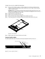
Figure 78. Operator information panel cable connection
The following notes describe additional information when you install the cable:
• To connect the operator information panel cable on the system board, press evenly on the cable.
Pressing on one side of the cable might cause damage to the cable or connector.
• The operator information panel cable must pass through the chassis latch between fan 3 and
fan 4 in order not to impede the fan cage.
Step 6.
Replace the cover (see “Replacing the cover” on page 190).
Step 7.
Slide the server into the rack.
Step 8.
Reconnect the power cords and any cables that you removed.
Step 9.
Turn on the peripheral devices and the server.
Completing the installation
Use this information to complete the installation.
To complete the installation, complete the following steps:
Step 1.
If you removed the air baffle, reinstall it (see “Replacing the air baffle” on page 90).
Step 2.
If you removed the server cover, replace it (see “Replacing the cover” on page 90).
Step 3.
Install the server in the rack cabinet (see the
Rack Installation Instructions
that comes with the
server for instructions).
Step 4.
Reconnect the cables and power cords (see “Connecting the cables” on page 91).
89
Summary of Contents for x3550 M4
Page 1: ...System x3550 M4 Installation and Service Guide Machine Type 7914 ...
Page 6: ...iv System x3550 M4 Installation and Service Guide ...
Page 178: ...164 System x3550 M4 Installation and Service Guide ...
Page 322: ...308 System x3550 M4 Installation and Service Guide ...
Page 828: ...814 System x3550 M4 Installation and Service Guide ...
Page 986: ...972 System x3550 M4 Installation and Service Guide ...
Page 990: ...976 System x3550 M4 Installation and Service Guide ...
Page 1005: ......
Page 1006: ......


