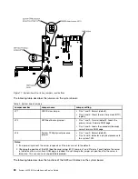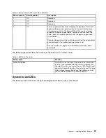
Table 3. System board SW3 switch block definition
Switch number
Default position
Description
1
Off
Reserved.
2
Off
Reserved.
3
Off
Reserved.
4
Off
Power-on password override. Changing the position of this switch
bypasses the power-on password check the next time the server
is turned on and starts the Setup utility so that you can change
or delete the power-on password. You do not have to move the
switch back to the default position after the power-on password
in overridden.
Changing the position of this switch does not affect the administrator
password check if an administrator password is set.
See “Passwords” on page 101 for additional information about
passwords.
The following table describes the functions of the button on the system board.
Table 4. Button on the server
Button name
Function
Force NMI button
This button is on the rear of the server. Press this button
to force a nonmaskable interrupt to the microprocessor.
You might have to use a pen or the end of a straightened
paper clip to press the button. You can also use it to force
a blue-screen memory dump (use this button only when
you are directed to do so by Lenovo Support).
System-board LEDs
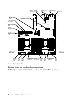
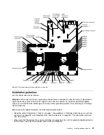
The following illustration shows the light-emitting diodes (LEDs) on the system board.
29
Summary of Contents for x3550 M4
Page 1: ...System x3550 M4 Installation and Service Guide Machine Type 7914 ...
Page 6: ...iv System x3550 M4 Installation and Service Guide ...
Page 178: ...164 System x3550 M4 Installation and Service Guide ...
Page 322: ...308 System x3550 M4 Installation and Service Guide ...
Page 828: ...814 System x3550 M4 Installation and Service Guide ...
Page 986: ...972 System x3550 M4 Installation and Service Guide ...
Page 990: ...976 System x3550 M4 Installation and Service Guide ...
Page 1005: ......
Page 1006: ......


