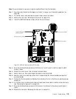
Step 13. Reconnect the power cord and any cables that you removed.
Step 14. Restart the server. The system begins the power-on self-test (POST). If this does not recover the
primary bank, continue with the following steps.
Step 15. Remove the top cover (see “Removing the top cover” on page 149).
Step 16. Reset the CMOS by removing the coin-cell battery (also called CMOS battery). See “Removing
the coin-cell battery (also called CMOS battery)” on page 255.
Step 17. Leave the coin-cell battery out of the server for approximately 5 to 15 minutes.
Step 18. Reinstall the coin-cell battery (see “Replacing the coin-cell battery (also called CMOS battery)” on
Step 19. Reinstall the top cover (see “Replacing the top cover” on page 151).
Step 20. Reconnect the power cord and any cables that you removed.
Step 21. Restart the server. The system begins the power-on self-test (POST).
Step 22. If these recovery efforts fail, contact your service representative for support.
In-band automated boot recovery method
This section details the in-band automated boot recovery method.
Note:
Use this method if the BOARD LED on the light path diagnostics panel is lit and there is a log entry
or
Booting Backup Image
is displayed on the firmware splash screen; otherwise, use the in-band manual
recovery method.
Step 1.
Boot the server to an operating system that is supported by the firmware update package that
you downloaded.
Step 2.
Perform the firmware update by following the instructions that are in the firmware update package
readme file.
Step 3.
Restart the server.
Step 4.
At the firmware splash screen, press F3 when prompted to restore to the primary bank. The
server boots from the primary bank.
Out-of-band method
See the IMM2 documentation (
Integrated Management Module II User's Guide
) at
Automated boot recovery (ABR)
Use this information for Automated boot recovery (ABR).
While the server is starting, if the integrated management module II detects problems with the server
firmware in the primary bank, the server automatically switches to the backup firmware bank and gives
you the opportunity to recover the firmware in the primary bank. For instructions for recovering the UEFI
firmware, see “Recovering the server firmware (UEFI update failure)” on page 108. After you have recovered
the firmware in the primary bank, complete the following steps:
Step 1.
Restart the server.
Step 2.
When the prompt
Press F3 to restore to primary
is displayed, press F3 to start the server from
the primary bank.
110
Lenovo System x3650 M5 Installation and Service Guide
Summary of Contents for x3650 M5
Page 1: ...Lenovo System x3650 M5 Installation and Service Guide Machine Type 8871 ...
Page 47: ...Figure 35 System board switches jumpers and buttons Chapter 1 The System x3650 M5 server 35 ...
Page 60: ...48 Lenovo System x3650 M5 Installation and Service Guide ...
Page 80: ...68 Lenovo System x3650 M5 Installation and Service Guide ...
Page 124: ...112 Lenovo System x3650 M5 Installation and Service Guide ...
Page 146: ...134 Lenovo System x3650 M5 Installation and Service Guide ...
Page 1322: ...1310 Lenovo System x3650 M5 Installation and Service Guide ...
Page 1330: ...Taiwan BSMI RoHS declaration 1318 Lenovo System x3650 M5 Installation and Service Guide ...
Page 1339: ......
Page 1340: ......


