


• The server supports one ultra-slim SATA optical drive.
Note:
The optical drive is available only on some models.
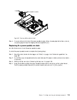
To install an optional optical drive, complete the following steps:
Step 1.
Read the safety information that begins on “Safety” on page v and “Installation guidelines” on
page 297.
Step 2.
Turn off the server and peripheral devices and disconnect the power cords and all external cables.
Note:
When you disconnect the power source from the server, you lose the ability to view the LEDs
because the LEDs are not lit when the power source is removed. Before you disconnect the
power source, make a note of which LEDs are lit, including the LEDs that are lit on the operation
information panel, and LEDs inside the server on the system board.
Step 3.
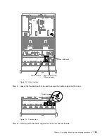
Remove the top cover (see “Removing the top cover” on page 149).
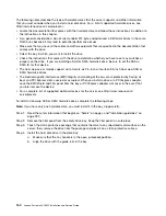
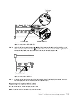
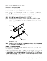
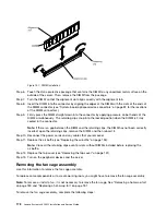
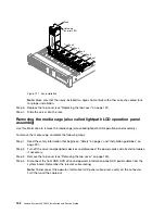
Step 4.
Remove the optical drive filler panel if it is installed. Locate the blue release tab on the rear of
the optical drive filler panel; then, while you press the tab, push the optical drive filler panel out
of the drive bay.
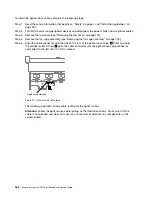
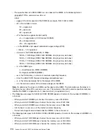
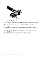
Step 5.
Remove the retention clip from the side of the optical drive filler panel. Save the optical drive filler
panel for future use.
Note:
If you are installing an optical drive that contains a laser, observe the following safety
precautions.
Statement 3
CAUTION:
When laser products (such as CD-ROMs, optical drives, fiber optic devices, or transmitters)
are installed, note the following:
• Do not remove the covers. Removing the covers of the laser product could result in
exposure to hazardous laser radiation. There are no serviceable parts inside the device.
• Use of controls or adjustments or performance of procedures other than those specified
herein might result in hazardous radiation exposure.
DANGER
Some laser products contain an embedded Class 3A or Class 3B laser diode. Note the
following.
Laser radiation when open. Do not stare into the beam, do not view directly with optical
instruments, and avoid direct exposure to the beam.
Installing, removing, and replacing components
169
Summary of Contents for x3650 M5
Page 1: ...Lenovo System x3650 M5 Installation and Service Guide Machine Type 8871 ...
Page 47: ...Figure 35 System board switches jumpers and buttons Chapter 1 The System x3650 M5 server 35 ...
Page 60: ...48 Lenovo System x3650 M5 Installation and Service Guide ...
Page 80: ...68 Lenovo System x3650 M5 Installation and Service Guide ...
Page 124: ...112 Lenovo System x3650 M5 Installation and Service Guide ...
Page 146: ...134 Lenovo System x3650 M5 Installation and Service Guide ...
Page 1322: ...1310 Lenovo System x3650 M5 Installation and Service Guide ...
Page 1330: ...Taiwan BSMI RoHS declaration 1318 Lenovo System x3650 M5 Installation and Service Guide ...
Page 1339: ......
Page 1340: ......


