


000000000000000
000000000000000
000000000000000
000000000000000
000000000000000
000000000000000
000000000000000
000000000000000
000000000000000
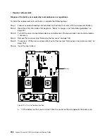
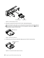
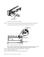
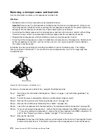
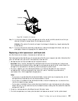
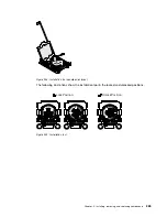
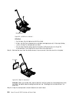
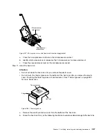
Operator information
panel assembly
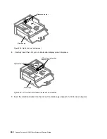
Figure 234. Operator information panel installation
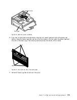
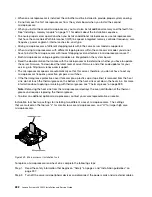
Step 5.
Inside the server, connect the operator information panel assembly cable to the system board.
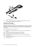
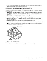
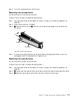
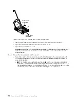
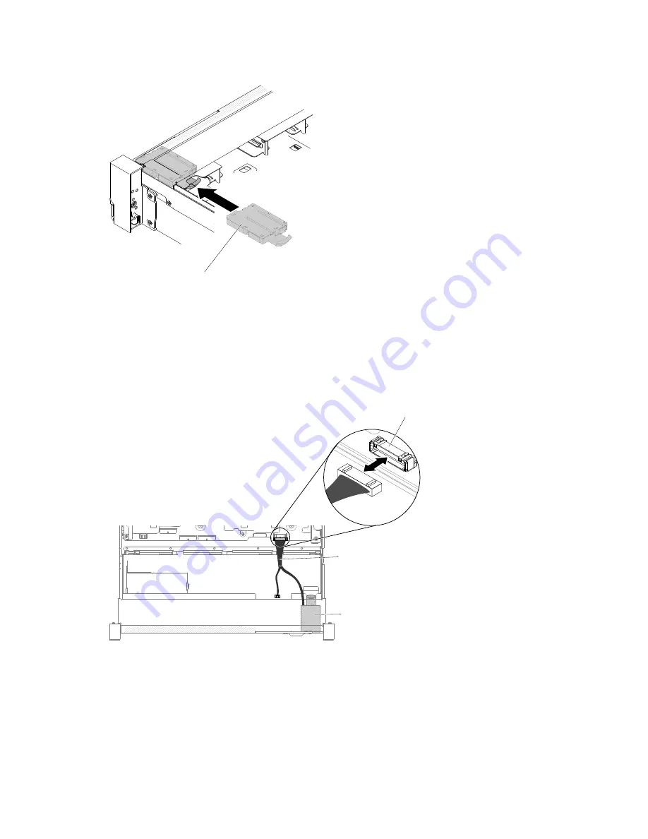
The following illustration shows the cable routing for the operator information panel.
0000000000000000000
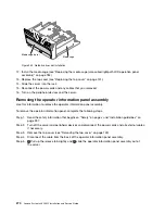
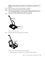
Operator information /
LCD panel connector
Operator information /
LCD panel cable
Operator information
panel assembly
Figure 235. Operator information panel cable routing
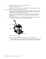
Note:
To connect the operator information panel cable on the system board, press evenly on the
cable. Pressing on one side of the cable might cause damage to the cable or connector.
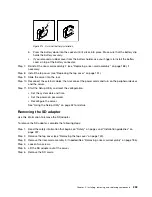
Step 6.
Replace the top cover (see “Replacing the top cover” on page 151).
Step 7.
Slide the server into the rack.
Step 8.
Reconnect the power cords and any cables that you removed.
272
Lenovo System x3650 M5 Installation and Service Guide
Summary of Contents for x3650 M5
Page 1: ...Lenovo System x3650 M5 Installation and Service Guide Machine Type 8871 ...
Page 47: ...Figure 35 System board switches jumpers and buttons Chapter 1 The System x3650 M5 server 35 ...
Page 60: ...48 Lenovo System x3650 M5 Installation and Service Guide ...
Page 80: ...68 Lenovo System x3650 M5 Installation and Service Guide ...
Page 124: ...112 Lenovo System x3650 M5 Installation and Service Guide ...
Page 146: ...134 Lenovo System x3650 M5 Installation and Service Guide ...
Page 1322: ...1310 Lenovo System x3650 M5 Installation and Service Guide ...
Page 1330: ...Taiwan BSMI RoHS declaration 1318 Lenovo System x3650 M5 Installation and Service Guide ...
Page 1339: ......
Page 1340: ......


