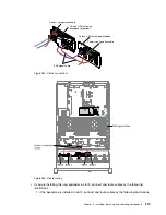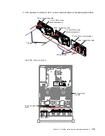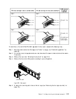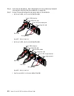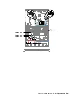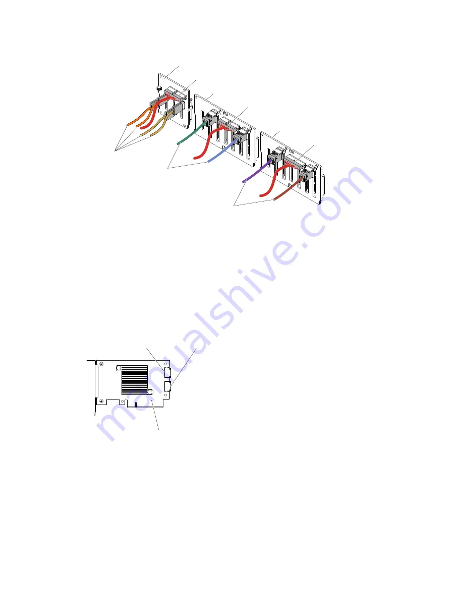
2.5-inch HDD hot-swap backplane
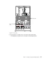
Power / configuration cable
SAS signal cable
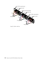
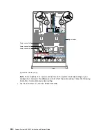
Power / configuration cable
Signal cable
2.5-inch NVMe backplane
2.5-inch HDD hot-swap backplane
Power / configuration cable
SAS signal cable
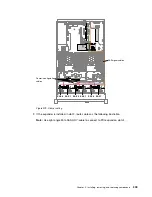
Figure 293. Cable connections
Step 8.
Touch the static-protective package that contains the NVMe adapter to any unpainted metal
surface on the server. Then, remove the NVMe adapter from the package.
Step 9.
Remove the PCI riser-card assemblies. (see “Removing a riser-card assembly” on page 186).
Step 10. Install NVMe adapters into the PCI connectors on the PCI riser card or the system board (see
“Replacing an adapter” on page 196).
Attention:
Incomplete insertion might cause damage to the server or the adapter.
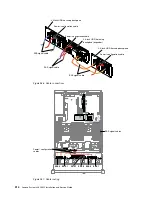
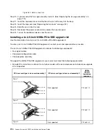
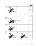
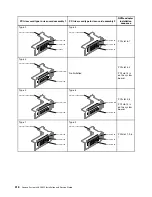
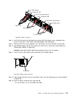
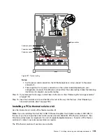
Step 11. Connect the four signal cables to the connectors on the NVMe adapter:
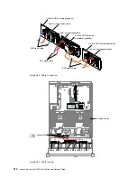
NVMe adapter
Port 1
Port 0
Figure 294. NVMe adapter connectors
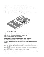
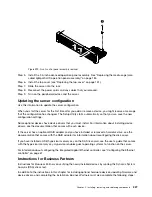
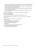
Step 12. Align and install the PCI riser-card assemblies in the server (see “Replacing a riser-card assembly”
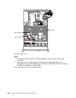
Step 13. Route the cables underneath the cable retention.
• 8x 2.5-inch HDD + 4x 2.5-inch NVMe PCIe SSD
Installing, removing, and replacing components
321
Summary of Contents for x3650 M5
Page 1: ...Lenovo System x3650 M5 Installation and Service Guide Machine Type 8871 ...
Page 47: ...Figure 35 System board switches jumpers and buttons Chapter 1 The System x3650 M5 server 35 ...
Page 60: ...48 Lenovo System x3650 M5 Installation and Service Guide ...
Page 80: ...68 Lenovo System x3650 M5 Installation and Service Guide ...
Page 124: ...112 Lenovo System x3650 M5 Installation and Service Guide ...
Page 146: ...134 Lenovo System x3650 M5 Installation and Service Guide ...
Page 1322: ...1310 Lenovo System x3650 M5 Installation and Service Guide ...
Page 1330: ...Taiwan BSMI RoHS declaration 1318 Lenovo System x3650 M5 Installation and Service Guide ...
Page 1339: ......
Page 1340: ......

