00000000000000000
00000000000000000
00000000000000000
00000000000000000
00000000000000000
00000000000000000
00000000000000000
00000000000000000
00000000000000000
00000000000000000
00000000000000000
00000
00000
00000
00000
0000
0000
0000
0000
0000
0000
0000
0000
0000
0000
0000
0000
0000
0000
0000
0000
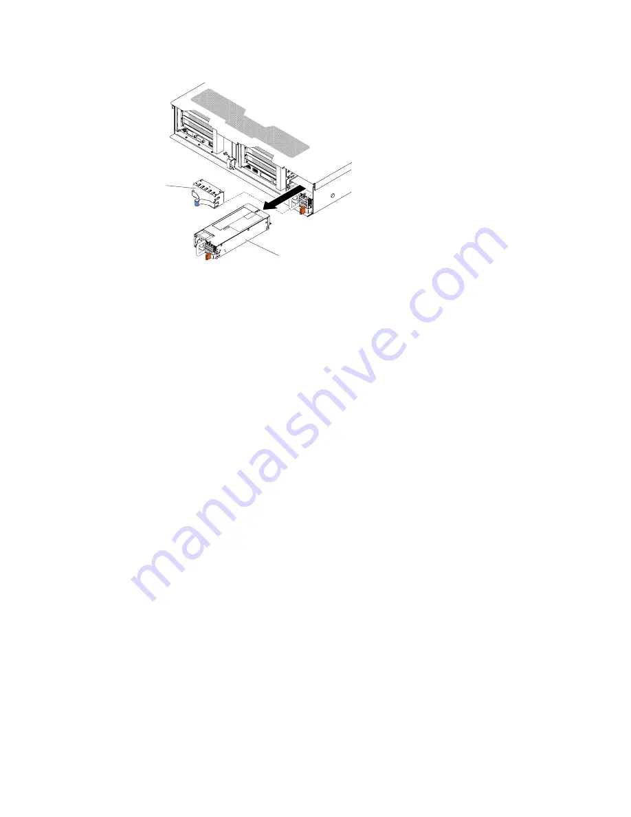
Hot-swap
power supply 2
Power supply
filler panel
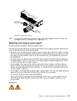
Figure 198. Power supply removal
Step 5.
If you are instructed to return the power supply, follow all packaging instructions, and use any
packaging materials for shipping that are supplied to you.
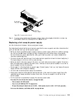
Replacing a hot-swap dc power supply
Use this information to replace a hot-swap dc power supply.
The following notes describe the type of power supply that the server supports and other information that
you must consider when you install a power supply:
• Before you install an additional power supply or replace a power supply with one of a different wattage,
you may use the IBM Power Configurator utility to determine current system power consumption.
For more information and to download the utility, go to http://www.ibm.com/ systems/bladecenter/
resources/ powerconfig.html.
• The server comes with one hot-swap 12-volt output power supply that connects to power supply bay 1.
The input voltage is -48 V dc or -60 V dc auto-sensing.
• Before you install a dc power supply in the server, you must remove all ac power supplies. Do not use
both ac and dc power supplies in the same server. Install up to two dc power supplies or up to two ac
power supplies, but not a combination.
• Power supply 1 is the default/primary power supply. If power supply 1 fails, you must replace the power
supply with the same wattage immediately.
• You can order an optional power supply for redundancy.
• These power supplies are designed for parallel operation. In the event of a power-supply failure, the
redundant power supply continues to power the system. The server supports a maximum of two
power supplies.
• It is the customer's responsibility to supply the necessary power cable.
To reduce the risk of electric shock or energy hazards:
–
Use a proper circuit breaker.
–
Use 4 mm
2
(10 AWG) at 90° C copper wire.
–
Torque the wiring-terminal screws to 0.50 ~ 0.60 newton-meters (4.43 ~ 5.31 inch-pounds).
For more information, see Statement 34 on page below.
Installing, removing, and replacing components
243
Summary of Contents for x3650 M5
Page 1: ...Lenovo System x3650 M5 Installation and Service Guide Machine Type 8871 ...
Page 47: ...Figure 35 System board switches jumpers and buttons Chapter 1 The System x3650 M5 server 35 ...
Page 60: ...48 Lenovo System x3650 M5 Installation and Service Guide ...
Page 80: ...68 Lenovo System x3650 M5 Installation and Service Guide ...
Page 124: ...112 Lenovo System x3650 M5 Installation and Service Guide ...
Page 146: ...134 Lenovo System x3650 M5 Installation and Service Guide ...
Page 1322: ...1310 Lenovo System x3650 M5 Installation and Service Guide ...
Page 1330: ...Taiwan BSMI RoHS declaration 1318 Lenovo System x3650 M5 Installation and Service Guide ...
Page 1339: ......
Page 1340: ......

