Removing a microprocessor and heat sink
Use this information to remove a microprocessor and heat sink.
Attention:
• Microprocessors are to be removed only by trained technicians.
Important:
Always use the microprocessor installation tool to remove a microprocessor. Failing to use
the microprocessor installation tool may damage the microprocessor sockets on the system board. Any
damage to the microprocessor sockets may require replacing the system board.
• Do not allow the thermal grease on the microprocessor and heat sink to come in contact with anything.
Contact with any surface can compromise the thermal grease and the microprocessor socket.
• Dropping the microprocessor during installation or removal can damage the contacts.
• Do not touch the microprocessor contacts; handle the microprocessor by the edges only. Contaminants
on the microprocessor contacts, such as oil from your skin, can cause connection failures between
the contacts and the socket.
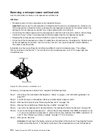
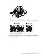
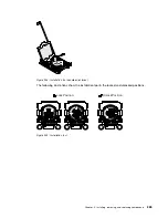
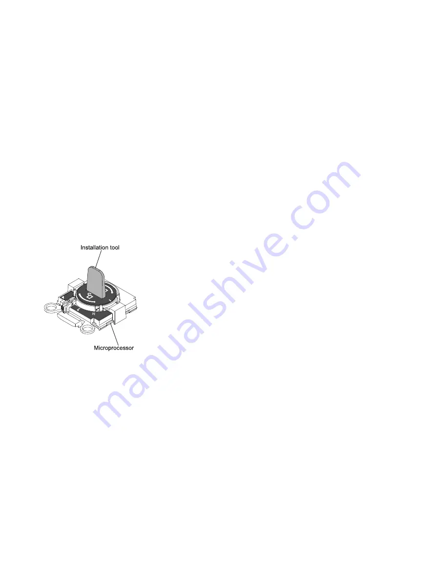
Installation tool has two settings for installing two different sizes of microprocessors. The settings
that are marked on the tool are “L” for smaller low core microprocessors, and “H” for larger high core
microprocessors.
H
Installation tool
Microprocessor
Figure 240. Microprocessor installation tools
To remove a microprocessor and heat sink, complete the following steps:
Step 1.
Read the safety information that begins on “Safety” on page v and “Installation guidelines” on
page 297.
Step 2.
Turn off the server and peripheral devices and disconnect all power cords.
Step 3.
Remove the top cover (see “Removing the top cover” on page 149).
Step 4.
Remove the air baffle (see “Removing the air baffle” on page 152).
Step 5.
Locate the microprocessor to be removed (see “System-board internal connectors” on page 29).
Step 6.
If you are removing microprocessor 1, remove the memory modules from DIMM connectors 6 and
7. If you are removing microprocessor 2, remove the memory modules from DIMM connectors 18
and 19. See “Removing a memory module” on page 171 for instructions.
Step 7.
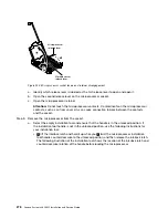
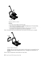
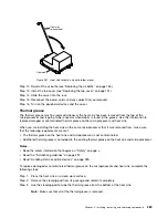
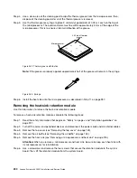
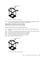
Remove the heat sink.
Attention:
Do not touch the thermal material on the bottom of the heat sink. Touching the thermal
material will contaminate it. If the thermal material on the microprocessor or heat sink becomes
276
Lenovo System x3650 M5 Installation and Service Guide
Summary of Contents for x3650 M5
Page 1: ...Lenovo System x3650 M5 Installation and Service Guide Machine Type 8871 ...
Page 47: ...Figure 35 System board switches jumpers and buttons Chapter 1 The System x3650 M5 server 35 ...
Page 60: ...48 Lenovo System x3650 M5 Installation and Service Guide ...
Page 80: ...68 Lenovo System x3650 M5 Installation and Service Guide ...
Page 124: ...112 Lenovo System x3650 M5 Installation and Service Guide ...
Page 146: ...134 Lenovo System x3650 M5 Installation and Service Guide ...
Page 1322: ...1310 Lenovo System x3650 M5 Installation and Service Guide ...
Page 1330: ...Taiwan BSMI RoHS declaration 1318 Lenovo System x3650 M5 Installation and Service Guide ...
Page 1339: ......
Page 1340: ......

