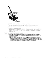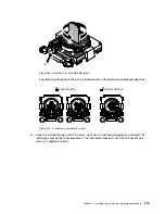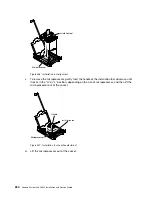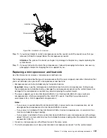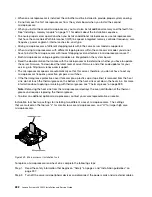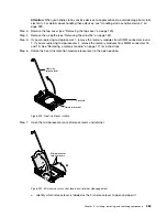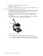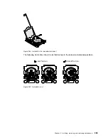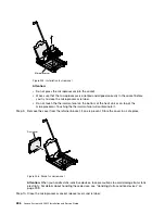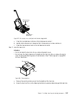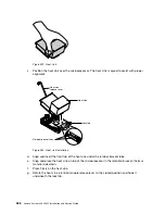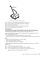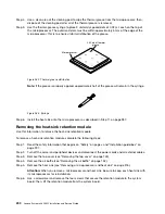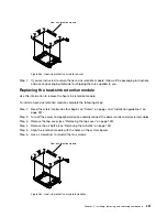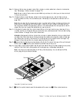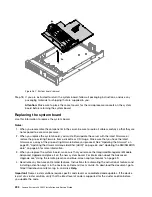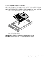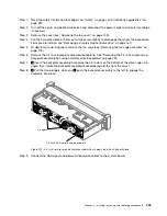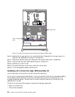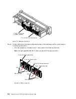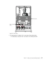
Step 7.
Reinstall the heat sink (see “Replacing a microprocessor and heat sink” on page 281).
Attention:
Make sure that you install each heat sink with its paired microprocessor.
Step 8.
Reinstall the air baffle (see “Replacing the air baffle” on page 153).
Step 9.
Install the top cover (see “Replacing the top cover” on page 151).
Step 10. Slide the server into the rack.
Step 11. Reconnect the power cords and any cables that you removed.
Step 12. Turn on the peripheral devices and the server.
Removing the system board
Use this information to remove the system board.
Notes:
1. When you replace the system board, you must either update the server with the latest firmware or
restore the pre-existing firmware that the customer provides on a diskette or CD image. Make sure that
you have the latest firmware or a copy of the pre-existing firmware before you proceed.
2. When you replace the system board, make sure that you remove the Integrated Management Module
Advanced Upgrade and place it on the new system board. For information about the Advanced
Upgrade, see “Using the remote presence and blue-screen capture features” on page 59.
3. Before you replace the system board, make sure that you back up any features on demand (FoD) keys
that were enabled. Reactivate any Features on Demand features. Instructions for automating the
activation of features and installing activation keys is in the
Features on Demand User's Guide
. To
download the document, go to https://fod.lenovo.com/lkms, log in, and click
Help
.
To remove the system board, complete the following steps:
Step 1.
Read the safety information that begins on “Safety” on page v, “Handling static-sensitive devices”
on page 299, and “Installation guidelines” on page 297.
Step 2.
Turn off the server and any attached devices.
Step 3.
Turn off the peripheral devices and disconnect all power cords.
Note:
When you replace the system board, you must either update the server with the latest
firmware or restore the pre-existing firmware that the customer provides on a diskette or CD
image. Make sure that you have the latest firmware or a copy of the pre-existing firmware before
you proceed.
Step 4.
Pull the power supplies out of the rear of the server, just enough to disengage them from the server.
Step 5.
Remove the top cover (see “Removing the top cover” on page 149).
Step 6.
Remove all PCI riser-card assemblies and adapters (see “Removing a riser-card assembly” on
page 186 and “Removing an adapter” on page 192).
Step 7.
Remove the air baffle (see “Removing the air baffle” on page 152).
Step 8.
Remove the fan cage assembly (See “Removing the fan cage assembly” on page 178).
Step 9.
Remove any backplate assembly or any backplane (See “Removing the 2.5-inch simple-swap
backplate assembly/hot-swap hard disk drive backplane” on page 248 and “Removing the 3.5-inch
simple-swap backplate assembly/hot-swap hard disk drive backplane” on page 250).
Step 10. Remove the dedicate slotless RAID controller (see “Removing the dedicated slotless RAID
Step 11. Remove the paddle card module (see “Removing the power paddle module” on page 154).
292
Lenovo System x3650 M5 Installation and Service Guide
Summary of Contents for x3650 M5
Page 1: ...Lenovo System x3650 M5 Installation and Service Guide Machine Type 8871 ...
Page 47: ...Figure 35 System board switches jumpers and buttons Chapter 1 The System x3650 M5 server 35 ...
Page 60: ...48 Lenovo System x3650 M5 Installation and Service Guide ...
Page 80: ...68 Lenovo System x3650 M5 Installation and Service Guide ...
Page 124: ...112 Lenovo System x3650 M5 Installation and Service Guide ...
Page 146: ...134 Lenovo System x3650 M5 Installation and Service Guide ...
Page 1322: ...1310 Lenovo System x3650 M5 Installation and Service Guide ...
Page 1330: ...Taiwan BSMI RoHS declaration 1318 Lenovo System x3650 M5 Installation and Service Guide ...
Page 1339: ......
Page 1340: ......

