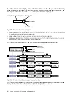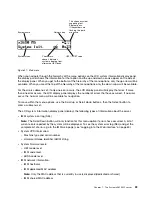
– IP v4 information
– IP v6 address
• System environmental information:
– Ambient temperature
– CPU temperature
– AC input voltage
– Estimated power consumption
Rear view
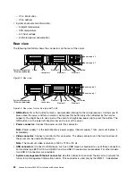
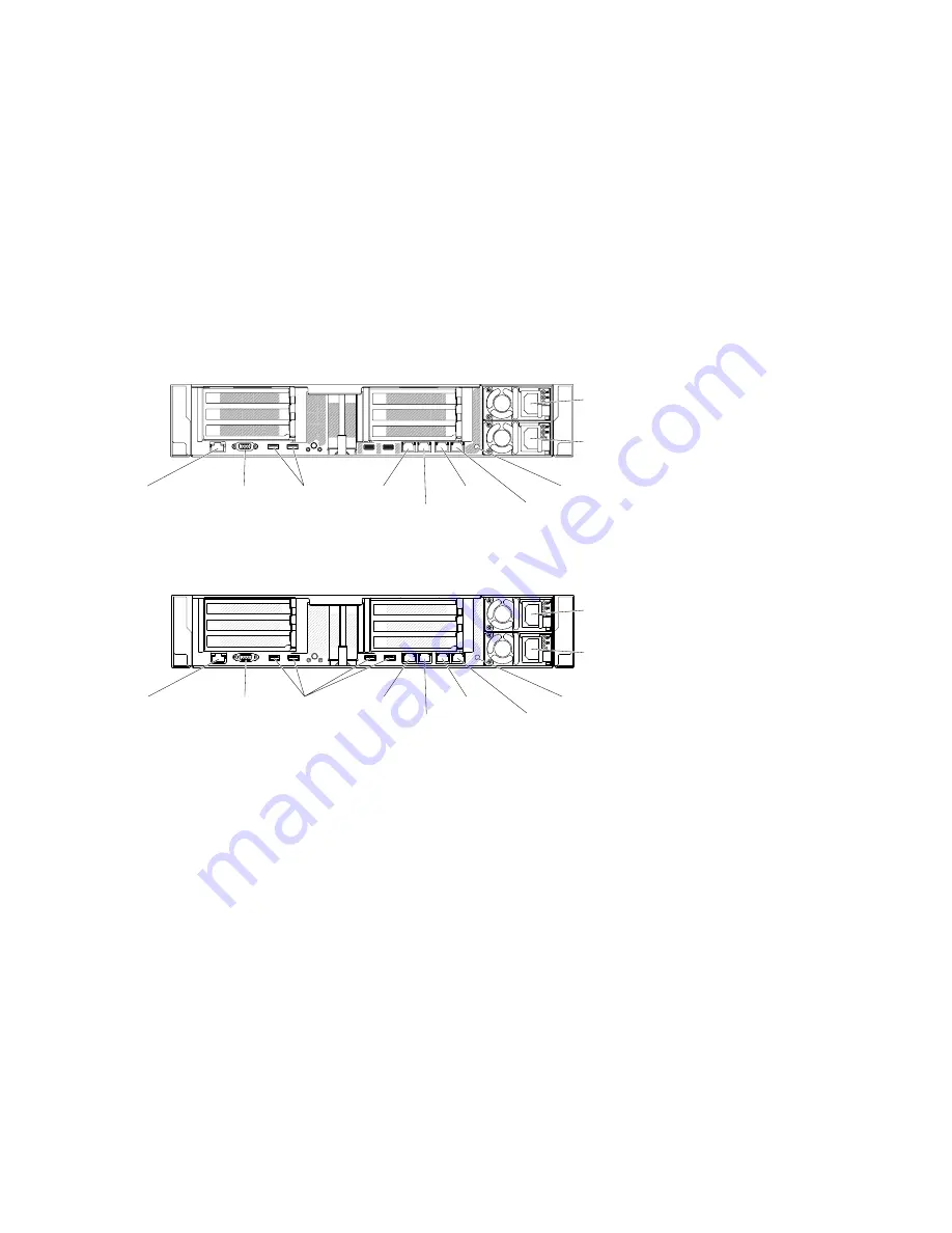
The following illustration shows the connectors on the rear of the server.
000000
000000
000000
00
00
00
00
00
00
0
0
0
0
0
0
0
0
000
000
000
000
000
000000
000000
000000
USB
connectors
Video
Ethernet 1
Ethernet 2
Ethernet 3
Ethernet 4
System-management
/ Ethernet (dedicated)
NMI button
Power supply 1
Power supply 2
000000
0000000
000000
Figure 22. Rear view
000000
000000
000000
000
000
000
000
000
000
0
0
0
0
0
0
0
0
000
000
000
000
000
0000000
0000000
0000000
USB
connectors
Video
Ethernet 1
Ethernet 2
Ethernet 3
Ethernet 4
System-management
/ Ethernet (dedicated)
NMI button
Power supply 1
Power supply 2
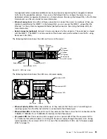
Figure 23. Rear view: for machine type 8871-AC3
•
NMI button:
Press this button to force a nonmaskable interrupt to the microprocessor. It allows you to
blue screen the server and take a memory dump (use this button only when directed by the service
support). You might have to use a pen or the end of a straightened paper clip to press the button. The
NMI button is in the lower left-hand corner on the rear of the server.
•
Power connector:
Connect the power cord to this connector.
Note:
Power supply 1 is the default/primary power supply. If power supply 1 fails, you must replace it
immediately.
•
Video connector:
Connect a monitor to this connector. The video connectors on the front and rear of
the server can be used simultaneously.
Note:
The maximum video resolution is 1600 x 1200 at 75 Hz.
•
USB connectors :
Connect a USB device, such as a USB mouse or keyboard to any of these connectors.
For machine type 8871-AC3, two USB 3.0 and two USB 2.0 connectors are provided. For other models,
two USB 3.0 connectors are provided.
•
Systems-management Ethernet connector:
Use this connector to connect the server to a network for
full systems-management information control. This connector is used only by the IMM2.1. A dedicated
24
Lenovo System x3650 M5 Installation and Service Guide
Summary of Contents for x3650 M5
Page 1: ...Lenovo System x3650 M5 Installation and Service Guide Machine Type 8871 ...
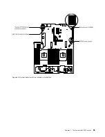
Page 47: ...Figure 35 System board switches jumpers and buttons Chapter 1 The System x3650 M5 server 35 ...
Page 60: ...48 Lenovo System x3650 M5 Installation and Service Guide ...
Page 80: ...68 Lenovo System x3650 M5 Installation and Service Guide ...
Page 124: ...112 Lenovo System x3650 M5 Installation and Service Guide ...
Page 146: ...134 Lenovo System x3650 M5 Installation and Service Guide ...
Page 1322: ...1310 Lenovo System x3650 M5 Installation and Service Guide ...
Page 1330: ...Taiwan BSMI RoHS declaration 1318 Lenovo System x3650 M5 Installation and Service Guide ...
Page 1339: ......
Page 1340: ......

