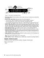
•
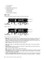
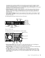
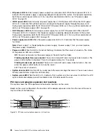
DC power LED:
Each hot-swap ac power supply has a dc power LED. When the dc power LED is lit, it
indicates that the power supply is supplying adequate dc power to the system. During typical operation,
both the ac and dc power LEDs are lit. For any other combination of LEDs, see “DC power-supply
LEDs” on page 76.
•
IN OK power LED:
Each hot-swap dc power supply has an IN OK power LED. When the IN OK power
LED is lit, it indicates that sufficient power is coming into the power supply through the power cord.
During typical operation, both the IN OK and OUT OK power LEDs are lit. For any other combination of
LEDs, see “DC power-supply LEDs” on page 76.
•
OUT OK power LED:
Each hot-swap dc power supply has an OUT OK power LED. When the OUT
OK power LED is lit, it indicates that the power supply is supplying adequate dc power to the system.
During typical operation, both the IN OK and OUT OK power LEDs are lit. For any other combination of
LEDs, see “DC power-supply LEDs” on page 76.
•
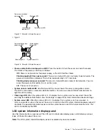
Power-supply error LED:
When the power-supply error LED is lit, it indicates that the power supply
has failed.
Note:
Power supply 1 is the default/primary power supply. If power supply 1 fails, you must replace
the power supply immediately.
•
Power-on LED:
When this LED is lit and not flashing, it indicates that the server is turned on. The states
of the power-on LED are as follows:
Off:
Power is not present, or the power supply or the LED itself has failed.
Flashing rapidly (4 times per second):
The server is turned off and is not ready to be turned on. The
power-control button is disabled. This will last approximately 5 to 10 seconds.
Flashing slowly (once per second):
The server is turned off and is ready to be turned on. You can
press the power-control button to turn on the server.
Lit:
The server is turned on.
•
System-locator LED:
Use this LED to visually locate the server among other servers. You can use Lenovo
XClarity Administrator to light this LED remotely.
•
System-error LED:
When this LED is lit, it indicates that a system error has occurred. An LED on the LCD
system information display panel (if available) is also lit to help isolate the error.
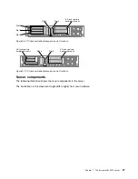
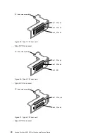
PCI riser-card adapter expansion slot locations
The section shows the PCI expansion slot connector locations on the server.
Based on the server configuration, the locations of the adapter expansion slots from the rear of the server
may be either of the following.
000000
000000
000000
000000
000000
000000
00
00
00
00
00
00
00
0
0
0
0
0
0
0
0
0
0
00
00
00
00
00
000000
000000
000000
000000
000000
000000
Slot 1
Slot 2
Slot 3
Slot 6
Slot 7
Slot 8
Slot 4
Slot 5
000000
000000
000000
000000
000000
000000
Figure 25. PCI riser-card adapter expansion slot locations
26
Lenovo System x3650 M5 Installation and Service Guide
Summary of Contents for x3650 M5
Page 1: ...Lenovo System x3650 M5 Installation and Service Guide Machine Type 8871 ...
Page 47: ...Figure 35 System board switches jumpers and buttons Chapter 1 The System x3650 M5 server 35 ...
Page 60: ...48 Lenovo System x3650 M5 Installation and Service Guide ...
Page 80: ...68 Lenovo System x3650 M5 Installation and Service Guide ...
Page 124: ...112 Lenovo System x3650 M5 Installation and Service Guide ...
Page 146: ...134 Lenovo System x3650 M5 Installation and Service Guide ...
Page 1322: ...1310 Lenovo System x3650 M5 Installation and Service Guide ...
Page 1330: ...Taiwan BSMI RoHS declaration 1318 Lenovo System x3650 M5 Installation and Service Guide ...
Page 1339: ......
Page 1340: ......

