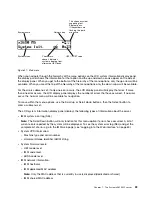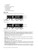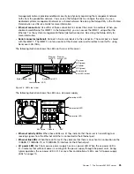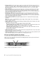
hot-swap components.) See the instructions for removing or installing a specific hot-swap component for
any additional procedures that you might have to perform before you remove or install the component.
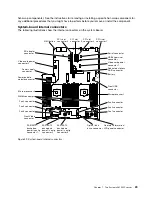
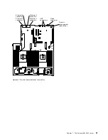
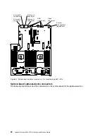
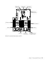
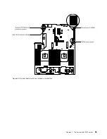
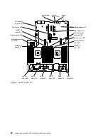
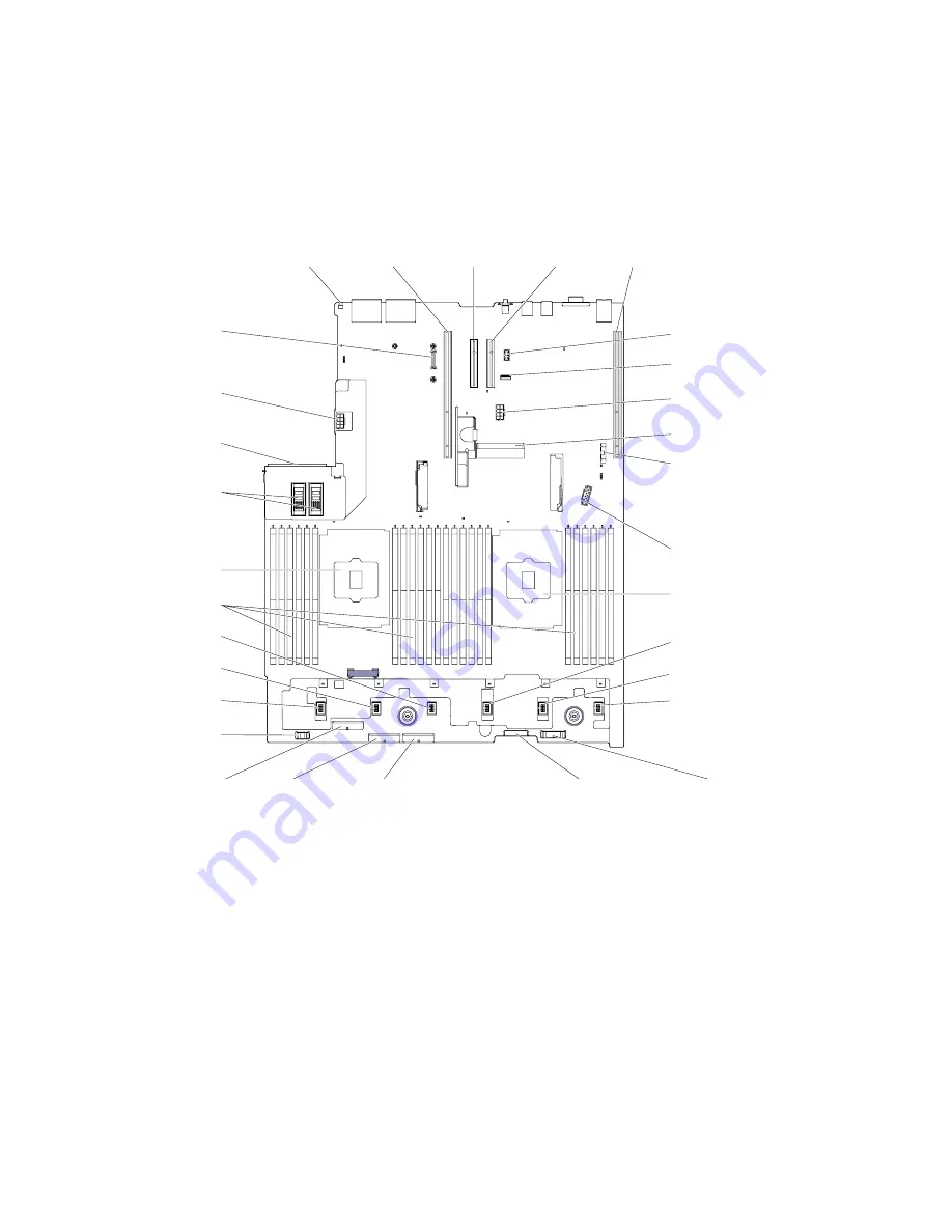
System-board internal connectors
The following illustrations show the internal connectors on the system board.
Dedicated slotless
RAID connector
Optical disk
drive connector
Operator information /
LCD panel connector
PCI riser
connector 1
PCI riser
connector 2
Video card power
connector 2
USB hypervisor
connector
Power paddle
module connector
Microprocessor 2
Fan 6 connector
Fan 3 connector
Fan 2 connector
Fan 1 connector
Front USB
connector
Front Video
connector
Microprocessor 1
DIMM connectors
NMI button
Battery
PCI slot
connector 4
PCI slot
connector 5
Fan 4 connector
Fan 5 connector
Power supply
connector
SAS/SATA
backplane
power / config
connector 3
SAS/SATA
backplane
power / config
connector 2
SAS/SATA
backplane
power / config
connector 1
Video card power
connector 1
Serial connector
SD adapter
connector
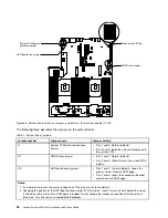
Figure 29. System-board internal connectors
29
Summary of Contents for x3650 M5
Page 1: ...Lenovo System x3650 M5 Installation and Service Guide Machine Type 8871 ...
Page 47: ...Figure 35 System board switches jumpers and buttons Chapter 1 The System x3650 M5 server 35 ...
Page 60: ...48 Lenovo System x3650 M5 Installation and Service Guide ...
Page 80: ...68 Lenovo System x3650 M5 Installation and Service Guide ...
Page 124: ...112 Lenovo System x3650 M5 Installation and Service Guide ...
Page 146: ...134 Lenovo System x3650 M5 Installation and Service Guide ...
Page 1322: ...1310 Lenovo System x3650 M5 Installation and Service Guide ...
Page 1330: ...Taiwan BSMI RoHS declaration 1318 Lenovo System x3650 M5 Installation and Service Guide ...
Page 1339: ......
Page 1340: ......

