44
Lenovo YOGA 910-13IKB/Lenovo YOGA 910-13IKB Glass
Hardware Maintenance Manual
1080 Thermal module
For access, remove these FRUs in order:
•
•
“1020 Battery pack” on page 33
•
“1030 Solid state disk” on page 35
•
“1040 PCI Express Mini Card for wireless LAN” on page 36
•
•
•
“1070 System board” on page 42
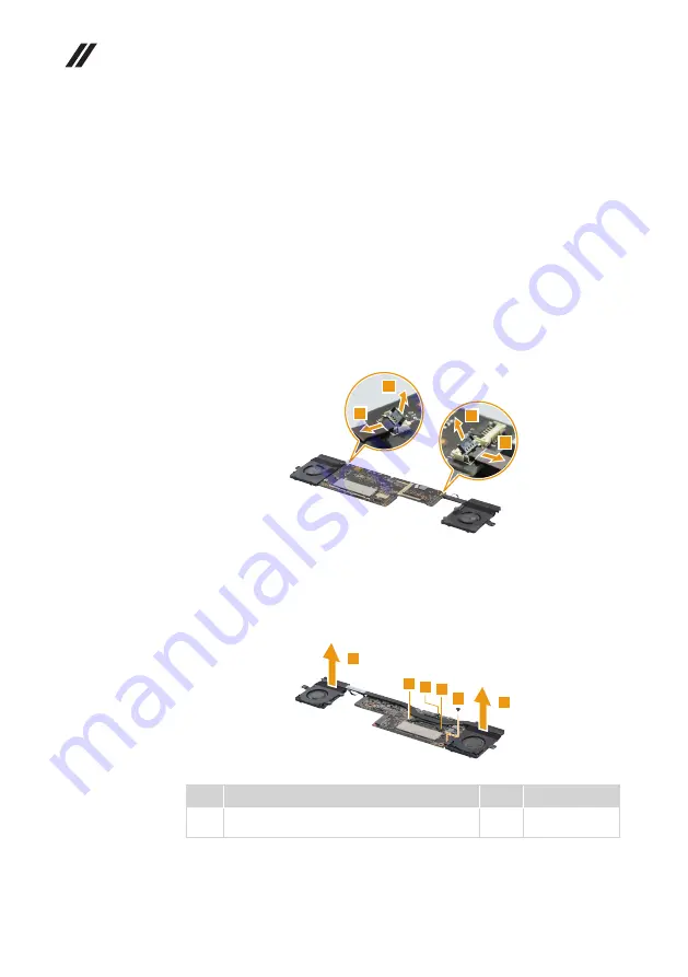
Figure 8. Removal steps of thermal module
Disconnect the two fan connectors in the directions shown by arrows
1
and
2
.
2
1
2
1
When installing:
Make sure that the connectors are attached firmly.
Turn the system board over. Remove the screw
3
and loosen the screws
4
.
Then remove the thermal module in the direction shown by arrow
5
.
3
4
4 4
5
5
Step Screw (quantity)
Color Torque
3
M2.0 x 2.7 mm, Phillips-head, nylok-coated (1)
Thermal Module to C Cover/MB
Black
1.8-2.0 kg_cm
Attention:
Do not handle the heat sink assembly roughly. Improper handling
can cause distortion or deformation and imperfect contact with components.


